Checking Main Relay, with pics!!!
#1
Honda-Tech Member
Thread Starter
Join Date: Sep 2002
Location: Central Point, Oregon, United States
Posts: 912
Likes: 0
Received 1 Like
on
1 Post
Mods should post this in FAQ!
1991 Honda Civic Hatchback L4-1.5L SOHC (16 valve)
Testing and Inspection
NOTE: If the car starts and continues to run, the PGM-FI main relay is OK.
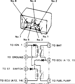
NOTE: Pay close attention to the diodes!!! This just bit me. Power can flow only one way through a diode. The diodes are the triangle arrow looking symbols in the Main relay diagram. The 'arrow' is the direction of current flow from positive to negative. Guess I should of read the directions more closely.
MAIN RELAY TEST
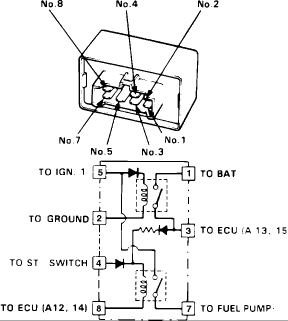
1. Remove the main relay.
2. Attach the positive battery terminal to the #4 terminal and the negative battery terminal to the #8 terminal of the main relay. Then check for continuity between the #5 terminal and the #7 terminal of the main relay.
a. If there is continuity, go to step 3.
b. If there is no continuity, replace the relay and retest.
3. Attach the positive battery terminal to the #5 terminal and the negative battery terminal to the #2 terminal of the main relay. Then check for continuity between the #1 terminal and the #3 terminal of the main relay.
a. If there is continuity, go to step 4.
b.If there is no continuity, replace the relay and retest.
4. Attach the positive battery terminal to the #3 terminal and the negative battery terminal to the #8 terminal of the main relay. Then check for continuity between the #5 terminal and the #7 terminal of the main relay.
a. If there is continuity, the relay is OK.
b. If the fuel pump still does not work, go to harness test.
c. If there is no continuity, replace the relay and retest.
MAIN RELAY HARNESS TEST
1. Keep the ignition switch in the OFF position.
2. Disconnect the main relay electrical connector.
3. Check for continuity between the BLACK wire (pin 2) in the connector and body ground.
Fig. 33 Main Relay Harness Test (pins 1 and 2)
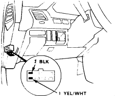
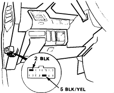
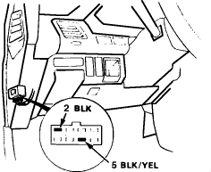
Fig. 34 Main Relay Harness Test (pins 2 and 5)
4. Attach the positive probe of the voltmeter to the YELLOW/WHITE wire (pin 1) and the negative probe to the BLACK wire (pin 2).
a. Battery voltage should be available.
b. If there is no voltage, check the wiring between the battery and the main relay as well as the ECU fuse (15A) in the main fuse box.
5. Attach the positive probe of the voltmeter to the BLACK/YELLOW wire (pin 5) and the negative probe to the BLACK wire (pin 2).
6. Turn the ignition switch ON.
a. Battery voltage should be available.
b. If there is no voltage available, check #14 fuse and the wiring from the ignition switch to the fuse box, and the wiring from the fuse box to the main relay.
7. Attach the positive probe of the voltmeter to the BLUE/WHITE wire (pin 4) and the negative probe to the BLACK wire (pin 2).
Fig. 35 Main Relay Harness Test (pins 2 and 4)
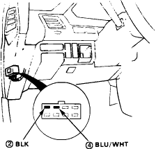
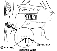
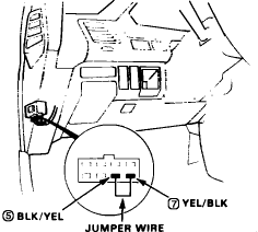
Fig. 36 Main Relay Harness Jumper Test
8. Turn the ignition switch to the START position.
a. Approximately 10 volts should be available.
b. If there is no voltage check the #2 (10A) fuse and the wiring between the ignition switch and the fuse box, and from the fuse box to the main relay.
9. Connect a jumper wire between the BLACK/YELLOW wire (pin 5) and the YELLOW/BLACK wire (pin 7).
10. Turn the ignition switch ON.
a. The fuel pump should work.
b. If the fuel pump does not work, check the wiring between the main relay and the fuel pump, and the wiring from the fuel pump to the ground (BLACK wire).
This is for a 1991 Civic hatch, but all 88-91 civic are checked the same. I just double checked. 92+ are different have a different main relay. They look exactly the same, but the 88-91's have pin 6 missing (making 7 pins total) and 92+ have pin 4 missing (again 7 pins total). So hope this helps somebody. I know I couldn't find anything that helped me test my main relay last night, so that's why I did this.
1991 Honda Civic Hatchback L4-1.5L SOHC (16 valve)
Testing and Inspection
NOTE: If the car starts and continues to run, the PGM-FI main relay is OK.
NOTE: Pay close attention to the diodes!!! This just bit me. Power can flow only one way through a diode. The diodes are the triangle arrow looking symbols in the Main relay diagram. The 'arrow' is the direction of current flow from positive to negative. Guess I should of read the directions more closely.

MAIN RELAY TEST

1. Remove the main relay.
2. Attach the positive battery terminal to the #4 terminal and the negative battery terminal to the #8 terminal of the main relay. Then check for continuity between the #5 terminal and the #7 terminal of the main relay.
a. If there is continuity, go to step 3.
b. If there is no continuity, replace the relay and retest.
3. Attach the positive battery terminal to the #5 terminal and the negative battery terminal to the #2 terminal of the main relay. Then check for continuity between the #1 terminal and the #3 terminal of the main relay.
a. If there is continuity, go to step 4.
b.If there is no continuity, replace the relay and retest.
4. Attach the positive battery terminal to the #3 terminal and the negative battery terminal to the #8 terminal of the main relay. Then check for continuity between the #5 terminal and the #7 terminal of the main relay.
a. If there is continuity, the relay is OK.
b. If the fuel pump still does not work, go to harness test.
c. If there is no continuity, replace the relay and retest.
MAIN RELAY HARNESS TEST
1. Keep the ignition switch in the OFF position.
2. Disconnect the main relay electrical connector.
3. Check for continuity between the BLACK wire (pin 2) in the connector and body ground.
Fig. 33 Main Relay Harness Test (pins 1 and 2)

Fig. 34 Main Relay Harness Test (pins 2 and 5)

4. Attach the positive probe of the voltmeter to the YELLOW/WHITE wire (pin 1) and the negative probe to the BLACK wire (pin 2).
a. Battery voltage should be available.
b. If there is no voltage, check the wiring between the battery and the main relay as well as the ECU fuse (15A) in the main fuse box.
5. Attach the positive probe of the voltmeter to the BLACK/YELLOW wire (pin 5) and the negative probe to the BLACK wire (pin 2).
6. Turn the ignition switch ON.
a. Battery voltage should be available.
b. If there is no voltage available, check #14 fuse and the wiring from the ignition switch to the fuse box, and the wiring from the fuse box to the main relay.
7. Attach the positive probe of the voltmeter to the BLUE/WHITE wire (pin 4) and the negative probe to the BLACK wire (pin 2).
Fig. 35 Main Relay Harness Test (pins 2 and 4)

Fig. 36 Main Relay Harness Jumper Test

8. Turn the ignition switch to the START position.
a. Approximately 10 volts should be available.
b. If there is no voltage check the #2 (10A) fuse and the wiring between the ignition switch and the fuse box, and from the fuse box to the main relay.
9. Connect a jumper wire between the BLACK/YELLOW wire (pin 5) and the YELLOW/BLACK wire (pin 7).
10. Turn the ignition switch ON.
a. The fuel pump should work.
b. If the fuel pump does not work, check the wiring between the main relay and the fuel pump, and the wiring from the fuel pump to the ground (BLACK wire).
This is for a 1991 Civic hatch, but all 88-91 civic are checked the same. I just double checked. 92+ are different have a different main relay. They look exactly the same, but the 88-91's have pin 6 missing (making 7 pins total) and 92+ have pin 4 missing (again 7 pins total). So hope this helps somebody. I know I couldn't find anything that helped me test my main relay last night, so that's why I did this.
Last edited by Ahknodd; 03-27-2009 at 02:30 PM. Reason: Edited with updated info... 88-91 and 92+ main relays are different!!
The following users liked this post:
#5
Honda-Tech Member
Thread Starter
Join Date: Sep 2002
Location: Central Point, Oregon, United States
Posts: 912
Likes: 0
Received 1 Like
on
1 Post
No, that was my bad for not covering my A$$. I just double checked with a 91 civic hatch and the testing is indeed different and so are the main relays! So a 92+ main relay won't work in a 88-91 car. Kinda interesting since they look exactly the same. 

#6
Honda-Tech Member
Join Date: Jan 2006
Location: Seattle, WA, USA
Posts: 11
Likes: 0
Received 0 Likes
on
0 Posts
Hello Ahknodd, thanks for this info. I have an 87 accord LXI and the relay testing procedure is exactly the same. My relay was ok, but my manual doesn't provide any info about where all these # connected to. It doesn't tell me how to test the harness either. So with your info I found that my ignition(#5) doesn't have continuity when connect to ground(#2), but when jumping ignition(#5) to fuel pump(#7), fuel rushed out really fast(The only test that I get fuel- I disconnect the fuel feeding line and inserted in a big cup). I don't have much time to figure this out ,cause I need the car tomorrow, nor the knowledge as to how the harness is wired(still confused how could there b no continuity between #5 and #2, but gets fuel when jumping #5 and #7). So can I ask you to check whether what I did was ok? I made a set of 5 wires with one end female and the other male, then I use them to connect between the harness and the relay for #1, #3, #4, #7, and #8. However, for the ground, I connect one end to the relay and the other end to the chassis and for the ignition, I wired it directly from the battery to the relay. Now I get the fuel when I connected to the relay using this ignition (instead of the ignition from the harness) and a lot of fuel when I turn the key to "start". So the only thing left to do is passing the ignition wire via a toggle switch. So I will have to turn on this switch before I start the engine and leave it on until I turn the engine off, then I make sure I turn off this switch.
So is there a problem doing this?
Thanks in advance.
So is there a problem doing this?
Thanks in advance.
#7
Honda-Tech Member
iTrader: (2)
Join Date: Nov 2007
Location: Pasadena, CA, USA
Posts: 7,217
Likes: 0
Received 0 Likes
on
0 Posts
NOTE: Pay close attention to the diodes!!! This just bit me. Power can flow only one way through a diode. The diodes are the triangle arrow looking symbols in the Main relay diagram. The 'arrow' is the direction of current flow from positive to negative. Guess I should of read the directions more closely.
Diodes act like one way valves for electrical current. You give out false information, and you should really educate yourself. There are three simple rules to remember about diodes.
1. Cathode (side with the stripe)
2. Anode (side without the stripe)
3. Anytime the cathode is more positive than the anode, no current will flow.
I guess you should educate yourself a lot more before wanting false information given out to everyone on Honda-tech.
Trending Topics
#8
Honda-Tech Member
Join Date: Dec 2005
Location: Thunder Bay, ON, Canada
Posts: 375
Likes: 0
Received 0 Likes
on
0 Posts
Most main relay problems are intermittant. You could end up testing it when it is cool enough to work properly. When you have it out, make sure to look for hairline cracks in the solder joints. To rule them out completely, just re-heat each one adding a bit more solder. I find this actually works to fix most malfunctioning relays.
#9
Honda-Tech Member
Join Date: Jan 2006
Location: Seattle, WA, USA
Posts: 11
Likes: 0
Received 0 Likes
on
0 Posts
I have an 87 Accord LXI. The car died while I was driving. I found the problem to be fuel related. The fuel pump was working because when I jumped the ignition to fuel pump, fuel rushed out like a pint/5sec or so(the only test I ever get fuel). The ECU was working cause my friend's 88 LXI, not quite the same ECU, started right away when I tried my ECU on his car.The main relay was also working cause when I tested the main relay(the same procedure as the one provided here), all contacts clicked and all continuity were available. I even tested with a new relay to eliminate the relay problem completely. However, when the relay is connected to its harness, it's not clicking, so I suspect the problem lies in the harness. I then tested the harness' pins for continuity using the information from here, http://www.tegger.com/hondafaq/mainr...ion/index.html . The following continuity test were done ; 1st test, between pin1(battery) and pin2(Ground). 2nd test, between pin5(Ignition) and pin2,
3rd test,between pin4(starter switch) and pin2, and 4th test, jumping pin5 to pin7(fuel pump).
When I disconnect the ECU, the relay harness test shows perfect result(as you supposed to get when a car is normal), but when ECU is connected, I got weird results and that's the reason why the relay was not activated(no clicking sound). There are 3 harness connected to the ECU, but only the connection of the middle one make the differences. Hope I didn't confuse anyone, the harness being tested is the relay harness, but the harness that (seems to) caused the problem(to the relay harness) is the ECU harness.
Here' s the results for the 4 key positions(off, 1,2, and start)
(Note: little low on the battery voltage, but it doesn't take much to pump the fuel)
A. ECU (middle) harness was NOT connected.
1st test Pin1(to Battery) & pin2(to ECU always ground)
11V, 11V, 11V, 9V
2nd test, pin5(to Ignition)& pin2
0v, 10v, 11v, 9v
3rd test, pin4(to starter switch) & pin2
0v, 0v, 0v, 6v
4th test, jump pin5 to pin7(fuel pump)
fuel rushed out
So, all good, but then
B. With ECU (middle) harness connected.
1st test Pin1(to Battery) & pin2(to ECU always ground)
10V, 10V, 0V, 0V
2nd test, pin5(to Ignition)& pin2
All no continuity 0v, 0v, 0v, 0v
3rd test, pin4(to starter switch) & pin2
-0.4v, -0.4v, -10v, 0v
4th test, jump pin5 to pin7(fuel pump)
fuel rushed out
So my question is have anyone seen this problem? Do you happen to know what are the middle harness' wires connecting to the ECU?
I thought to fix this problem I might have to replace the whole set of under-dash wires, any suggestion?
Some info that might be helpful, I just replaced the head gasket on the car. At the beginning, I saw the cooling fan, may be wires, making sparks a few times, but I drove the car anyway. I drove it about 100 miles since then. And a few days, about 40 miles, right before the car died, I had to replace the alternator.
Thank you in advance
The weary man
#10
Junior Member
Join Date: Mar 2005
Location: Panama City, FL., USA
Posts: 238
Likes: 0
Received 0 Likes
on
0 Posts
Thanks for the quick reply, I will be doing these tests soon. have a great day, my wife just got laid off and I need to get this car running and gone!
#12
Mods should post this in FAQ!
1991 Honda Civic Hatchback L4-1.5L SOHC (16 valve)
Testing and Inspection
NOTE: If the car starts and continues to run, the PGM-FI main relay is OK.
NOTE: Pay close attention to the diodes!!! This just bit me. Power can flow only one way through a diode. The diodes are the triangle arrow looking symbols in the Main relay diagram. The 'arrow' is the direction of current flow from positive to negative. Guess I should of read the directions more closely.
MAIN RELAY TEST
1. Remove the main relay.
2. Attach the positive battery terminal to the #4 terminal and the negative battery terminal to the #8 terminal of the main relay. Then check for continuity between the #5 terminal and the #7 terminal of the main relay.
a. If there is continuity, go to step 3.
b. If there is no continuity, replace the relay and retest.
3. Attach the positive battery terminal to the #5 terminal and the negative battery terminal to the #2 terminal of the main relay. Then check for continuity between the #1 terminal and the #3 terminal of the main relay.
a. If there is continuity, go to step 4.
b.If there is no continuity, replace the relay and retest.
4. Attach the positive battery terminal to the #3 terminal and the negative battery terminal to the #8 terminal of the main relay. Then check for continuity between the #5 terminal and the #7 terminal of the main relay.
a. If there is continuity, the relay is OK.
b. If the fuel pump still does not work, go to harness test.
c. If there is no continuity, replace the relay and retest.
MAIN RELAY HARNESS TEST
1. Keep the ignition switch in the OFF position.
2. Disconnect the main relay electrical connector.
3. Check for continuity between the BLACK wire (pin 2) in the connector and body ground.
Fig. 33 Main Relay Harness Test (pins 1 and 2)
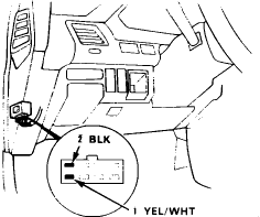
Fig. 34 Main Relay Harness Test (pins 2 and 5)
4. Attach the positive probe of the voltmeter to the YELLOW/WHITE wire (pin 1) and the negative probe to the BLACK wire (pin 2).
a. Battery voltage should be available.
b. If there is no voltage, check the wiring between the battery and the main relay as well as the ECU fuse (15A) in the main fuse box.
5. Attach the positive probe of the voltmeter to the BLACK/YELLOW wire (pin 5) and the negative probe to the BLACK wire (pin 2).
6. Turn the ignition switch ON.
a. Battery voltage should be available.
b. If there is no voltage available, check #14 fuse and the wiring from the ignition switch to the fuse box, and the wiring from the fuse box to the main relay.
7. Attach the positive probe of the voltmeter to the BLUE/WHITE wire (pin 4) and the negative probe to the BLACK wire (pin 2).
Fig. 35 Main Relay Harness Test (pins 2 and 4)
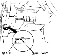
Fig. 36 Main Relay Harness Jumper Test
8. Turn the ignition switch to the START position.
a. Approximately 10 volts should be available.
b. If there is no voltage check the #2 (10A) fuse and the wiring between the ignition switch and the fuse box, and from the fuse box to the main relay.
9. Connect a jumper wire between the BLACK/YELLOW wire (pin 5) and the YELLOW/BLACK wire (pin 7).
10. Turn the ignition switch ON.
a. The fuel pump should work.
b. If the fuel pump does not work, check the wiring between the main relay and the fuel pump, and the wiring from the fuel pump to the ground (BLACK wire).
This is for a 1991 Civic hatch, but all 88-91 civic are checked the same. I just double checked. 92+ are different have a different main relay. They look exactly the same, but the 88-91's have pin 6 missing (making 7 pins total) and 92+ have pin 4 missing (again 7 pins total). So hope this helps somebody. I know I couldn't find anything that helped me test my main relay last night, so that's why I did this.
1991 Honda Civic Hatchback L4-1.5L SOHC (16 valve)
Testing and Inspection
NOTE: If the car starts and continues to run, the PGM-FI main relay is OK.
NOTE: Pay close attention to the diodes!!! This just bit me. Power can flow only one way through a diode. The diodes are the triangle arrow looking symbols in the Main relay diagram. The 'arrow' is the direction of current flow from positive to negative. Guess I should of read the directions more closely.

MAIN RELAY TEST

1. Remove the main relay.
2. Attach the positive battery terminal to the #4 terminal and the negative battery terminal to the #8 terminal of the main relay. Then check for continuity between the #5 terminal and the #7 terminal of the main relay.
a. If there is continuity, go to step 3.
b. If there is no continuity, replace the relay and retest.
3. Attach the positive battery terminal to the #5 terminal and the negative battery terminal to the #2 terminal of the main relay. Then check for continuity between the #1 terminal and the #3 terminal of the main relay.
a. If there is continuity, go to step 4.
b.If there is no continuity, replace the relay and retest.
4. Attach the positive battery terminal to the #3 terminal and the negative battery terminal to the #8 terminal of the main relay. Then check for continuity between the #5 terminal and the #7 terminal of the main relay.
a. If there is continuity, the relay is OK.
b. If the fuel pump still does not work, go to harness test.
c. If there is no continuity, replace the relay and retest.
MAIN RELAY HARNESS TEST
1. Keep the ignition switch in the OFF position.
2. Disconnect the main relay electrical connector.
3. Check for continuity between the BLACK wire (pin 2) in the connector and body ground.
Fig. 33 Main Relay Harness Test (pins 1 and 2)

Fig. 34 Main Relay Harness Test (pins 2 and 5)

4. Attach the positive probe of the voltmeter to the YELLOW/WHITE wire (pin 1) and the negative probe to the BLACK wire (pin 2).
a. Battery voltage should be available.
b. If there is no voltage, check the wiring between the battery and the main relay as well as the ECU fuse (15A) in the main fuse box.
5. Attach the positive probe of the voltmeter to the BLACK/YELLOW wire (pin 5) and the negative probe to the BLACK wire (pin 2).
6. Turn the ignition switch ON.
a. Battery voltage should be available.
b. If there is no voltage available, check #14 fuse and the wiring from the ignition switch to the fuse box, and the wiring from the fuse box to the main relay.
7. Attach the positive probe of the voltmeter to the BLUE/WHITE wire (pin 4) and the negative probe to the BLACK wire (pin 2).
Fig. 35 Main Relay Harness Test (pins 2 and 4)

Fig. 36 Main Relay Harness Jumper Test

8. Turn the ignition switch to the START position.
a. Approximately 10 volts should be available.
b. If there is no voltage check the #2 (10A) fuse and the wiring between the ignition switch and the fuse box, and from the fuse box to the main relay.
9. Connect a jumper wire between the BLACK/YELLOW wire (pin 5) and the YELLOW/BLACK wire (pin 7).
10. Turn the ignition switch ON.
a. The fuel pump should work.
b. If the fuel pump does not work, check the wiring between the main relay and the fuel pump, and the wiring from the fuel pump to the ground (BLACK wire).
This is for a 1991 Civic hatch, but all 88-91 civic are checked the same. I just double checked. 92+ are different have a different main relay. They look exactly the same, but the 88-91's have pin 6 missing (making 7 pins total) and 92+ have pin 4 missing (again 7 pins total). So hope this helps somebody. I know I couldn't find anything that helped me test my main relay last night, so that's why I did this.
#14
Honda-Tech Member
#15
Honda-Tech Member
absolutely not the main relay. look at the bigger one next to the one you are showing.
https://honda-tech.com/forums/honda-civic-del-sol-1992-2000-1/car-wont-start-running-out-ideas-2518263/
https://honda-tech.com/forums/honda-civic-del-sol-1992-2000-1/car-wont-start-running-out-ideas-2518263/
#18
Thank you for all the replies. I did locate it and the sauder was still in tact. I purchased a new main relay and the car runs better than when I bought it. However, the parts store said that there are two main relays and I may be wrong...this sight wasn't. Once again thank you! !!t
#20
ok so my problem was that i was getting no power to my fuel pump, and i did the jumper test in the harness and fuel pump came right on but I dont know how to fix it? and before i forget its a brand new relay
#21
I just got on this post because I have problems regarding the main relay for my 1994 Civic EX. The illustration of the relay and schematic do not represent what I have in my hand. I have a Mitsuba RZ-0132 (which is similar to a RZ-0159) and it does not have a #4 terminal and it does have a #6 terminal, both contradict the schematic shown.
What relay is the schematic for? Does someone have a schematic and test procedures for the the RZ-0132 relay? Please let me know. Thanks for the help.
John
What relay is the schematic for? Does someone have a schematic and test procedures for the the RZ-0132 relay? Please let me know. Thanks for the help.
John
#24
I had a bad main relay and repaired it. 1991 Honda threw a code 16. Checked main relay it was faulty. Found a link to rebuild the main relay. This worked like a charm. Here is the link from you tube.
Honda No Start? POSSIBLE Main Relay - EricTheCarGuy
www.youtube.com/watch?v=viIZ8k60awY
This worked for me and saved me $53. Good luck
Honda No Start? POSSIBLE Main Relay - EricTheCarGuy
www.youtube.com/watch?v=viIZ8k60awY
This worked for me and saved me $53. Good luck
#25
longest project ever
Join Date: Sep 2009
Location: on the south side of dixie, 1986 Accord Hatch
Posts: 3,494
Likes: 0
Received 2 Likes
on
2 Posts
one thing that confuses so many people, is that the ECU will only send power to the main relay for a couple of seconds to prime it, then while the car is being cranked, it detects that the engine is turning through the dizzy, and turns off the pump when it doesn't detect those pulses. This is a safety feature. Even carbed early Hondas without an ECU have a safety relay that does this same thing


