
Diffuser design
 10-22-2006, 07:24 AM
#1
Honda-Tech Member
Thread Starter
Join Date: May 2006
Location: gold coast, QLD, Australia
Posts: 117
Likes: 0
Received 0 Likes
on
0 Posts
Hey guys just got some quick questions that im sure somone here can answer.
im designing a diffuser, so have been learning as much as i possibly can from the internet about diffusers and aerodynamics in general, and want to confirm what i believe, not knowing if ive interpreted things correctly. Anyways...
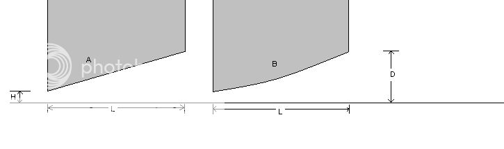
Its my understanding that for both A and B that if H,L & D are equal between the two, and there is no flow seperation for either example, then both would perform equally. Is this correct?
It is also my understanding that you could run a larger D with example B before flow seperation begins due to the curved roof and therefore get better performing design. Once again is this correct?
Thanks
Murray
im designing a diffuser, so have been learning as much as i possibly can from the internet about diffusers and aerodynamics in general, and want to confirm what i believe, not knowing if ive interpreted things correctly. Anyways...
Its my understanding that for both A and B that if H,L & D are equal between the two, and there is no flow seperation for either example, then both would perform equally. Is this correct?
It is also my understanding that you could run a larger D with example B before flow seperation begins due to the curved roof and therefore get better performing design. Once again is this correct?
Thanks
Murray
 10-22-2006, 07:47 AM
#2
Honda-Tech Member
Thread Starter
Join Date: May 2006
Location: gold coast, QLD, Australia
Posts: 117
Likes: 0
Received 0 Likes
on
0 Posts
Also reguarding setting a good angle (ive designed it so both H & D can be easily adjusted allowing angles from 5-25 degrees and adjustable inlet area).
Using tufts along the top surface, i take it you would travel at your max speed, increasing the angle each run until flow seperation begins, then back the angle off to the previous setting so no seperation is experianced at max speed??
how can u tell when seperation is occouring using the tufts??? im guessing that the tufts downstream from the flow seperation will be blowing in all directions, while the unseperated airflow will just blow the tufts toward the rear?
 10-22-2006, 08:21 AM
#4
Honda-Tech Member
Thread Starter
Join Date: May 2006
Location: gold coast, QLD, Australia
Posts: 117
Likes: 0
Received 0 Likes
on
0 Posts
<TABLE WIDTH="90%" CELLSPACING=0 CELLPADDING=0 ALIGN=CENTER><TR><TD>Quote, originally posted by kb58 »</TD></TR><TR><TD CLASS="quote">Another was to test (at the track) is to adjust the angles and watch for fastest lap time - that's really the goal!</TD></TR></TABLE> Yeah good point there 
10-22-2006, 08:28 AM
#5
Honda-Tech Member
Thread Starter
Join Date: May 2006
Location: gold coast, QLD, Australia
Posts: 117
Likes: 0
Received 0 Likes
on
0 Posts
anyone there have an answed for the first question, im really keen to get started on the prototype tonite. It would be harder to do the curved surface so naturally id prefer to do a flat roof, but if theres a performance advantage from it being curved than thats final. So the big question Curved or Flat???? can i run with a larger D (without flow seperation) from having a curved surface??
10-22-2006, 10:15 AM
#6
Join Date: Aug 2005
Location: In Da Doghouse
Posts: 109
Likes: 0
Received 0 Likes
on
0 Posts
You might get a more experienced answer over here
http://www.eng-tips.com/threadminder.cfm?pid=87
HTH
Donnie
10-22-2006, 11:12 AM
#7
Honda-Tech Member
Join Date: Feb 2002
Location: Orange, CALIFORNIA, USA
Posts: 1,642
Likes: 0
Received 0 Likes
on
0 Posts
The Special Projects Motor Sports Race Team, and our business will be moving in a whole new direction in 2007. We will be taking a totally different approach to our future Motor Racing involvement.
We will be starting on a couple of exciting new projects immediately after the SEMA Show in November. We will soon be looking for Team/Crew members. - Perhaps even some proven consistant test drivers if all goes according to plan?
Aerodynamics will be a major feature of these projects and we will be providing photographs, comprehensive working illustrations, and test results as we go. We have been quietly working away at our research, and our plans. We have, and will continue to consult with those who know their stuff, like Johny Mac and others. With their help, we should be able provide and share some of the information we have learned here, and when our new projects feature in some up coming magazine articles and possible TV Show.
Kiwi
Modified by KIWI at 5:08 PM 10/22/2006
Trending Topics
10-22-2006, 09:07 PM
#9
Honda-Tech Member
Thread Starter
Join Date: May 2006
Location: gold coast, QLD, Australia
Posts: 117
Likes: 0
Received 0 Likes
on
0 Posts
<TABLE WIDTH="90%" CELLSPACING=0 CELLPADDING=0 ALIGN=CENTER><TR><TD>Quote, originally posted by D Jaws II »</TD></TR><TR><TD CLASS="quote">
You might get a more experienced answer over here
http://www.eng-tips.com/threadminder.cfm?pid=87
HTH
Donnie
</TD></TR></TABLE>
thanks for that - its a great site
You might get a more experienced answer over here
http://www.eng-tips.com/threadminder.cfm?pid=87
HTH
Donnie
</TD></TR></TABLE>
thanks for that - its a great site
10-23-2006, 03:28 AM
#10
Honda-Tech Member
Thread Starter
Join Date: May 2006
Location: gold coast, QLD, Australia
Posts: 117
Likes: 0
Received 0 Likes
on
0 Posts
iv seen a couple of designs like this one, where the curve is inverted. i dont understand why it is curved in such a manner. is there a reason for it or is not not designed very well? the way i see it, doing this will cause a sharper change in angle at the beggining of the diffuser tunnel, making it more prone to flow seperation at that point. wouldnt it just be better to just use a flat roof?
10-23-2006, 11:26 AM
#11
Honda-Tech Member
Join Date: Oct 2006
Location: Toronto, ON, Canada
Posts: 31
Likes: 0
Received 0 Likes
on
0 Posts
I think its more for asthetics dude.
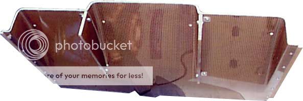
As you can see in this picture of the front of an Audi R8 diffuser the roof is curved, and naturally it would make sense to curve your diffuser to some point where the change in angle is occuring. I think a shap point at the transition from flat to the "roof" area would cause a lot of flow seperation, so try and avoid that.

As you can see in this picture of the front of an Audi R8 diffuser the roof is curved, and naturally it would make sense to curve your diffuser to some point where the change in angle is occuring. I think a shap point at the transition from flat to the "roof" area would cause a lot of flow seperation, so try and avoid that.
10-23-2006, 11:55 AM
#12

Join Date: Oct 2002
Location: Eagle Mountain, UT, USA
Posts: 1,708
Likes: 0
Received 0 Likes
on
0 Posts
I think the real question is what will happen with either example relative to your specific car. Mix and match each design on different cars and you may see completely different results. The better question is how will each example work with your aerodynamic system. I agree with KB the only way to know is to try it out unless you have a source for FEA or something like that. Is the bottom of your car flat from the front to the rear exit? How much air is just spilling out the sides? It seems to me a wing might make more sense if you are looking for some downforce.
10-23-2006, 12:31 PM
#13
My Name is Nobody
<TABLE WIDTH="90%" CELLSPACING=0 CELLPADDING=0 ALIGN=CENTER><TR><TD>Quote, originally posted by Muzz »</TD></TR><TR><TD CLASS="quote">Hey guys just got some quick questions that im sure somone here can answer.
im designing a diffuser, so have been learning as much as i possibly can from the internet about diffusers and aerodynamics in general, and want to confirm what i believe, not knowing if ive interpreted things correctly. Anyways...
Its my understanding that for both A and B that if H,L & D are equal between the two, and there is no flow seperation for either example, then both would perform equally. Is this correct?
It is also my understanding that you could run a larger D with example B before flow seperation begins due to the curved roof and therefore get better performing design. Once again is this correct?
Thanks
Murray
</TD></TR></TABLE>
you may be right in a pure environment (little advantage eitherway)... but reality there is a very important difference. One is not wrong and the other correct, they are simply different, and in addition you have left out alternative # C... a concave profile. The main difference lies is fluid dynamics... and what happens AFTER the air leaves the chamber... AERODYNAMIC DRAG.
Jef(Kiwi), if your intersted, I know some folks that are AeroSpace engineers
Modified by MSchu at 2:21 PM 10/23/2006
10-23-2006, 03:27 PM
#14
Honda-Tech Member
Join Date: Jan 2000
Location: Fort Worth, TX
Posts: 1,288
Likes: 0
Received 0 Likes
on
0 Posts
Go with the curved surface. You won't get much angle of attack out of the flat one without separating the flow.
As for flow separation, the easiest way to see it would be with a smoke wand, but that's hard outside a wind tunnel. I'd say just trial and error and see what you end up with.
Also keep in mind that you can extend the diffuser airfoil beyond the stock rear bumper to further expand the air behind the car and reduce drag by eliminating some suction on the rear of it.
10-23-2006, 03:57 PM
#15
Join Date: Oct 2002
Location: Eagle Mountain, UT, USA
Posts: 1,708
Likes: 0
Received 0 Likes
on
0 Posts
If the flow is all screwed up (turbulent) before it gets to the diff the shape isn't going to matter much. If the air smacks into your gas tank, exhuast and uneven underside of the car how will a diff be effective? How will you direct the air into the diff in a uniform way? Even if you were to create some downforce will the tradeoff in drag be worth the gains in downforce. Downforce will only matter over 100 mph and does your car have the power to offset the downforce or will it just make you slower? I would think in high speed sweepers you want to focus more on mechanical grip and keeping momentum at least with a normal Honda. Then again I'm not sure what car we are talking about here. I'll just stop posting about all this other stuff as you probably just want your specific question answered. I just think this is barking up the wrong tree thats all. Hell for all I know you may be talking about a high power formula car.
10-23-2006, 08:15 PM
#16
Honda-Tech Member
Thread Starter
Join Date: May 2006
Location: gold coast, QLD, Australia
Posts: 117
Likes: 0
Received 0 Likes
on
0 Posts
Im designing this for a EK civic hatchback (along with a super light flat underbody tray, which is more like an aluminium frame, with replaceable panels and replacable skirts) and also a front air dam and splitter (basicaly a hole aero package).
I dont plan to be using it on my car though till i finish uni in 3 years. As i am only just learning to drive at autocrosses and driver training days at the moment, and i still use this car on the road.
Im studing mechanical engineering at QUT in australia, majoring in motorsport engineering, and Im dying for the moment i finish so i can get a second car, and strip the civic down, and prep the chassis for circuit racing.
I figure that if i can make the undertray and diffuser together weigh under 10kg (i think thats about 20lb), so its not penalising me in weight much, if it gives a little more stability at super high speeds then it all adds up to a better race car. Who knows i may never end up using these pieces once i actually get to do some race track testing with them, or they may be illegal for the class i choose to race in. It dosnt bother me, i just love to design and create .
.
The thing i look forward to the most, more than actually racing even, is devloping, researching, testing and improving the chassis and suspension, after the driver, this is what makes a race car. i used to race remote control cars and the part i loved most about it all, more than the racing, was constantly working to improve the suspension/handling as a package. i can see myself more at the local track for the test and tune days trying to beat my own times, then the actual race days.
I dont plan to be using it on my car though till i finish uni in 3 years. As i am only just learning to drive at autocrosses and driver training days at the moment, and i still use this car on the road.
Im studing mechanical engineering at QUT in australia, majoring in motorsport engineering, and Im dying for the moment i finish so i can get a second car, and strip the civic down, and prep the chassis for circuit racing.
I figure that if i can make the undertray and diffuser together weigh under 10kg (i think thats about 20lb), so its not penalising me in weight much, if it gives a little more stability at super high speeds then it all adds up to a better race car. Who knows i may never end up using these pieces once i actually get to do some race track testing with them, or they may be illegal for the class i choose to race in. It dosnt bother me, i just love to design and create
. The thing i look forward to the most, more than actually racing even, is devloping, researching, testing and improving the chassis and suspension, after the driver, this is what makes a race car. i used to race remote control cars and the part i loved most about it all, more than the racing, was constantly working to improve the suspension/handling as a package. i can see myself more at the local track for the test and tune days trying to beat my own times, then the actual race days.
10-23-2006, 08:25 PM
#17
Honda-Tech Member
Thread Starter
Join Date: May 2006
Location: gold coast, QLD, Australia
Posts: 117
Likes: 0
Received 0 Likes
on
0 Posts
<TABLE WIDTH="90%" CELLSPACING=0 CELLPADDING=0 ALIGN=CENTER><TR><TD>Quote, originally posted by crx12 »</TD></TR><TR><TD CLASS="quote"> I'll just stop posting about all this other stuff as you probably just want your specific question answered. </TD></TR></TABLE>
No not at all im here to learn as much as i possibly can, and i really appreciate everyones opinion
No not at all im here to learn as much as i possibly can, and i really appreciate everyones opinion
10-23-2006, 08:57 PM
#18
Honda-Tech Member
Thread Starter
Join Date: May 2006
Location: gold coast, QLD, Australia
Posts: 117
Likes: 0
Received 0 Likes
on
0 Posts
<TABLE WIDTH="90%" CELLSPACING=0 CELLPADDING=0 ALIGN=CENTER><TR><TD>Quote, originally posted by crx12 »</TD></TR><TR><TD CLASS="quote"> Is the bottom of your car flat from the front to the rear exit? How much air is just spilling out the sides? It seems to me a wing might make more sense if you are looking for some downforce. </TD></TR></TABLE>
The bottom will be completly flat, with replacable skirts to get as close to the ground as possible, aswell as endplates for the diffuser reducing the amount of air getting sucked in from the sides.
i want to do a splitter/undertray/diffuser combo as from what iv read on the net, which could easily be false info , is that this will provide downforce across the entire chassis instead of just at where the wing is mounted.
Also i feel that this downforce, while still producing drag, dosnt increase frontal area of the car, which is a bonus.
One thing im real interested in is the ratio of downforce to drag for a well designed wing and a well designed under body, splitter & diffuser. I feel you would have less drag for the same amount of downforce with a Diffuser, but this is based on what i feel/recon, not what i know. If anyone does know the answer id love to know.
However im sure ill be playing around with a wing during the devolopment of my car, and id guess that big downforce is much easier to get with a wing, much more than a diffuser. I will be doing a fluid dynamics unit at uni in the second half of 2007 and i just cant wait what im designing now is more of a prototype to improve on.
The bottom will be completly flat, with replacable skirts to get as close to the ground as possible, aswell as endplates for the diffuser reducing the amount of air getting sucked in from the sides.
i want to do a splitter/undertray/diffuser combo as from what iv read on the net, which could easily be false info
, is that this will provide downforce across the entire chassis instead of just at where the wing is mounted. Also i feel that this downforce, while still producing drag, dosnt increase frontal area of the car, which is a bonus.
One thing im real interested in is the ratio of downforce to drag for a well designed wing and a well designed under body, splitter & diffuser. I feel you would have less drag for the same amount of downforce with a Diffuser, but this is based on what i feel/recon, not what i know. If anyone does know the answer id love to know.
However im sure ill be playing around with a wing during the devolopment of my car, and id guess that big downforce is much easier to get with a wing, much more than a diffuser. I will be doing a fluid dynamics unit at uni in the second half of 2007 and i just cant wait
what im designing now is more of a prototype to improve on.
10-25-2006, 02:59 PM
#19
Honda-Tech Member
Originally Posted by Muzz
Hey guys just got some quick questions that im sure somone here can answer.
im designing a diffuser, so have been learning as much as i possibly can from the internet about diffusers and aerodynamics in general, and want to confirm what i believe, not knowing if ive interpreted things correctly. Anyways...
Its my understanding that for both A and B that if H,L & D are equal between the two, and there is no flow seperation for either example, then both would perform equally. Is this correct?
It is also my understanding that you could run a larger D with example B before flow seperation begins due to the curved roof and therefore get better performing design. Once again is this correct?
Thanks
Murray
Your question is actually a very good one. Should you have curvature in the diffuser ceiling or should it be linear? The answer to this question is all-to-common "it depends". Both the linear and curved diffuser designs work, but the answer to what works better is that it depends on the flow in the afterbody region. In addition, the literature is a bit wanting in this area of showing just what kind of bodies one type of diffuser will work best on which type of car design. And, the studies on diffusers show some very interesting facts regarding how the air pressure varies as the flow moves towards the diffuser inlet.
Without going into too much detail, here are some facts regarding diffuser design:
Linear Diffuser Ceiling:
The linear diffuser is both the simplest and easiest to manufacture type of diffuser that works very well in most cases. If low drag is the aim, then the diffuser ceiling angle should be relatively small at something close to four or five degrees for most cars. This is generally true for cars that do not have a wing to help drive the underbody flow. At this ceiling angle, the flow usually stays attached to the ceiling and the flow exits relatively smoothly. If no fences (vertical fins) are used, the flow does have a three dimensional character characterized by the usual boundary layer flow couple with some spanwise movement of the airflow.
The other factor that should be considered is ride height, since it affects downforce and drag significantly. If the car is too high, the underbody flow is relatively slow and the resulting pressure is small (as seen in Bernoulli's law) and if the car is too low, then boundary layer effects cause flow blockage and the resulting high pressure there. Generally, the ride height should be close to .05*length of the car or roughly 6 inches for best overall performance of downforce to drag ratio.
Curved Upper Ceiling
On formula one cars, there is a huge low pressure region behind the car due mostly to the two or three element wings. This very large low pressure region can effectively drive the underbody flow with even steep ceiling angles and even though the adverse pressure gradient in such ceiling is high, the flow can still stay attached much longer due to the low pressure behind the cars wings. The curved diffusers help to fill in the aft body region with higher pressure air which helps to reduce drag, but also the high flow rate under the car helps to increase downforce. However, the ceiling design must be tested to know how much curvature will result in the best compromise of downforce to drag ratio. If the pressure is a little lower then the design moves towards a slightly less curved diffuser ceiling.
With all of this in mind, I think for your application that a nice linear diffuser angle with anywhere from seven to fourteen degrees of upslope angle could be used. If you can only use a small downforce wing (i.e. Cl < 1.5, A < 5 sq ft, V < 120 mph) then use a smaller diffuser angle for best results. A couple of fences can help improve downforce, especially at higher ceiling angles, by making the flow more two dimensional and helping to keep the flow attached to the ceiling since the fences help generate vorticies that energize the flow in the diffuser.
In you are able to mount you rear wing as rearward as possible, do so to help locate the low pressure nearer to the diffuser exit to further help the underbody flow. If you have any more specifics on your wing design (or if you need my assistance on this) please let me know. As with all things relating to racing, there will need to be compromises to find the best fit for each track. In effect, one downforce setting with the attendant drag will possibly work much better for one track than another and so if you are looking for one setup to work overall best, you need to sit downforce and analyze each track's corners and straights to come to a best compromise.
Hope this helps.
10-25-2006, 03:34 PM
#21
Honda-Tech Member
<TABLE WIDTH="90%" CELLSPACING=0 CELLPADDING=0 ALIGN=CENTER><TR><TD>Quote, originally posted by Tyson »</TD></TR><TR><TD CLASS="quote">i think its all about aesthetics.</TD></TR></TABLE>
Art = function, right?
Art = function, right?
10-27-2006, 03:07 AM
#22
Honda-Tech Member
Thread Starter
Join Date: May 2006
Location: gold coast, QLD, Australia
Posts: 117
Likes: 0
Received 0 Likes
on
0 Posts
thanks for that Johnny mac plenty of useful info i havnt yet come across in my search - very interesting.
plenty of useful info i havnt yet come across in my search - very interesting.
10-27-2006, 03:17 AM
#23
Honda-Tech Member
Thread Starter
Join Date: May 2006
Location: gold coast, QLD, Australia
Posts: 117
Likes: 0
Received 0 Likes
on
0 Posts
do u mind me asking how youve gained your knowedge on this subject? As in, did u study areodynamics as a uni corse, or was it a single subject of another type of uni course, learnt on the job etc. And also how long u have been studying it?
I ask this because one of my uni subjects is fluid dynamics, its a half year subject, and im not shur if it will cover the topic in as much depth as i am looking for.
Do you think half a year of study would be enough to be competent in aero design for racing cars etc.
murray
I ask this because one of my uni subjects is fluid dynamics, its a half year subject, and im not shur if it will cover the topic in as much depth as i am looking for.
Do you think half a year of study would be enough to be competent in aero design for racing cars etc.
murray
10-27-2006, 08:40 AM
#24
Honda-Tech Member
<TABLE WIDTH="90%" CELLSPACING=0 CELLPADDING=0 ALIGN=CENTER><TR><TD>Quote, originally posted by Muzz »</TD></TR><TR><TD CLASS="quote">do u mind me asking how youve gained your knowedge on this subject? As in, did u study areodynamics as a uni corse, or was it a single subject of another type of uni course, learnt on the job etc. And also how long u have been studying it?
I ask this because one of my uni subjects is fluid dynamics, its a half year subject, and im not shur if it will cover the topic in as much depth as i am looking for.
Do you think half a year of study would be enough to be competent in aero design for racing cars etc.
murray
</TD></TR></TABLE>
I studied fluid mechanics extensively while earning my BS and MS at UCLA in aerospace engineering (took the fluid mechanics route in aeronautics and not some of the other sub-specialties like spacecraft trajectory or others). I have been doing a PhD specifically in fluid mechanics on boundary layer separation methods for 3-Dimensional BL's and have been working on my own theory of BL transition projection for different type of fluid borne instabilities.
Because fluid mechanics is so very complex that we probably will never see an actual solution to turbulence, and being that real fluid flows are almost entirely turbulent (the laminar hypothesis is done to greatly simplify the math and concepts involved). Most good information on specific types of fluid flows is found in the professional journals such as "Journal of Aircraft", "Proceedings of ASME", ASME J. Fluids Engineering, SAE papers on fluid mechanics relating to car applications, and many, many others.
Most of the fluid mechanics you learn in undergraduate studies relates to relatively simple flows such as pipe flow, and using the Reynolds Transport Theorem to use control volumes for other simple flows. You will do some simple inviscid airfoil and if you're lucky you'll get to write a program to do some panel methods using sources, sinks, and potential vorticity to simulate flows around different types of bodies.
Unfortunately, none of what you'll learn will help much in designing diffusers since the flow is complex in that it is 3-Dimensional, it could separate at certain diffuser angles and using certain fence designs, and the inlet flow is particular complex due to boundary layer issues forward of the inlet.
To solve a problem like your diffuser problem, you should look for a journal paper of a blunt body on a moving ground plane that give some information about length and width of the body, and shows how the ride height can affect both the drag and downforce. Then, come up with a simple design and either go out and test on the actual full scale car or do some wind tunnel testing on a scale model to fine tune your results.
Remember, if you do not closely follow what was done in the journal paper, you're likely to get invalid results. For example, in the journal paper mention above, if the model does not have a wing then you probably will not get really good results if you use a wing on your car. This is because the wing futher drives the underbody flow and as such the boundary layer thickness under the car is less than it would be for model with no wing. This would tend to move the max downforce and max drag to a point of lower ride height. So you see, fluid mechanics is a very complex subject that continues to draw in great researchers due to the puzzle solving type of fun it involves.
10-29-2006, 03:34 AM
#25
Honda-Tech Member
Join Date: Jan 2003
Location: Cogito ergo sum, Canada
Posts: 1,979
Likes: 0
Received 0 Likes
on
0 Posts
Now assuming that Johnny is joking about a mere mortal having access to a wind tunnel to test out ideas for a diffuser on a Civic, one might get some ideas using tufts. I have never seen many write ups on methods a mere mortal could use, but this one came to mind. It is from the Team-Integra.net web site in a post about the best place to put your engine intake, and it was taken from Endyn's Archive, http://www.theoldone.com/archi...s.htm (although I didn't find the source)
"Cowl induction is a great way to intake outside air of ambient temperature. There is a high pressure area at the base of the windshield, and you need only turn your "climate control system" to outside and cool to appreciate the amount of pressure available there. I believe that for most normally aspirated cars, it's the optimum place to draw atmospheric "fuel" from.
I currently have a 3" diameter hole cut below the right hand parking light that simply allows air to enter the inner fender area with less restriction. We have constructed an air box which resides to the right of the battery, and it has a foam lip which seals to the underside of the hood. At the bottom and side of the air box, there are some holes, 2.75" dia. each to be exact. No attempt whatever was made to seal the inner fender gaps or to achieve "ram", I simply wanted ambient temperatures at positive (as opposed to negative) pressure. In this configuration, I don't sweat deep water, and it's been worth 18 hp in back to back from 45mph up in tests using our Vericom on our test track.
Measuring pressure is relatively simple to do.
I prefer to tuft test the car first, using a chase car with a camcorder. You need a wide road so the chase car will not adversely affect the flow over and around the front of the car.
Short pieces of yarn taped to the body work great...as long as the color contrasts with the car's color. You'll notice that the area above the bumper is almost "dead", however, the area under is very active. The area on top of the hood from the middle of the hood to the headlights is "dead" as well.
Now that you have some notion of where the air is active, determining pressure is simple. Assuming you do not have assess to manometers, buy a piece of plywood and cut it so it's 2' high and 2' long. Cut some wooden yard sticks down to 2', and use some "Hot Stuff" to attach 3 or 4 to the board in an evenly spaced vertical orientation. Buy about 20' of clear tubing and attach "U" shaped segments to the board using "U" shaped brads. Do not crush the tubing, and place it so the yard stick is between the legs of the "U" tubing. Do the same with the other 3. You now have 4 manometers or "U" tubes. Place the board in the interior of the car where it may be observed or taped. Fill each tube with water with a dash of red food coloring and a drop of soap to cut surface tension. when filling the tubes , fill them until the water level is at 12" on each leg of each tube. This is "0" pressure. Slip a short tube in one end of each "U" tube. Then slip a piece of clear tubing over the connector tube, and run it all the way to the area where you want to measure pressure. Tape the tubing to the body wherever necessary. If you want pressure at the front, aim the end of the tube forward, using your tuft test results to determine "forward" and duct tape the tube so it is aimed squarely at the on coming air. Place other tubes from the other manometers where ever you want to test pressure. Run the car up to various speeds and tape the amount of movement observed on each "U" tube, make sure that you accurately record the speed while recording the movement of water in the tubes, and make sure you run all the way to the top speed you feel is the maximum you'll be seeing in a race or what ever. Having someone call out the speeds and getting that on the tape is a good move.
The water column in each tube will have moved during this test, unless the pressure in the car is the same as where you tested on the exterior. What does it mean? The water in the test leg of the "U" will go down and the other side will rise if you are seeing positive pressure, the lower it goes and the higher on the positive side, the greater the pressure, and conversely, should the column rise, you're in a low or negative pressure zone, and you won't want to attempt to draw air there....it could actually attempt to suck air out of your intake.
I realize this may sound primitive, but we did it at Penske's and we've done tests like this hundreds of times in many cars. On small cars where budget allows, we simply place pressure transducers that are wired to the data recorder. When Bill Elliott run over 200 mph at Daytona, and 209 mph at Talledega...finally 213mph., everyone thought it was the engine, and it was. However, as we had no tunnel time prior to Daytona, we did what I've just described, and we found that at 197mph.
The pressure in the duct at the base of the windshield went away and became a vacuum. Some reworking of that entire area allowed us to see positive pressure past 220mph , and the rest is another story for another time, but it's attention to details throughout the "package" that generally make my combinations work, and my work doesn't come cheap, especially in todays "win at any price" pace. "
Another thing you might do is pick up the latest book by Simon McBeath:
Competition Car Aerodynamics: A practical handbook

It is full of very nice diagrams showing the 3D flow results on race cars using CFD simulation software, including wings, splitters, diffusers, etc. Pictures are sometimes so much better than words or equations to get an idea of what is going on.
"Cowl induction is a great way to intake outside air of ambient temperature. There is a high pressure area at the base of the windshield, and you need only turn your "climate control system" to outside and cool to appreciate the amount of pressure available there. I believe that for most normally aspirated cars, it's the optimum place to draw atmospheric "fuel" from.
I currently have a 3" diameter hole cut below the right hand parking light that simply allows air to enter the inner fender area with less restriction. We have constructed an air box which resides to the right of the battery, and it has a foam lip which seals to the underside of the hood. At the bottom and side of the air box, there are some holes, 2.75" dia. each to be exact. No attempt whatever was made to seal the inner fender gaps or to achieve "ram", I simply wanted ambient temperatures at positive (as opposed to negative) pressure. In this configuration, I don't sweat deep water, and it's been worth 18 hp in back to back from 45mph up in tests using our Vericom on our test track.
Measuring pressure is relatively simple to do.
I prefer to tuft test the car first, using a chase car with a camcorder. You need a wide road so the chase car will not adversely affect the flow over and around the front of the car.
Short pieces of yarn taped to the body work great...as long as the color contrasts with the car's color. You'll notice that the area above the bumper is almost "dead", however, the area under is very active. The area on top of the hood from the middle of the hood to the headlights is "dead" as well.
Now that you have some notion of where the air is active, determining pressure is simple. Assuming you do not have assess to manometers, buy a piece of plywood and cut it so it's 2' high and 2' long. Cut some wooden yard sticks down to 2', and use some "Hot Stuff" to attach 3 or 4 to the board in an evenly spaced vertical orientation. Buy about 20' of clear tubing and attach "U" shaped segments to the board using "U" shaped brads. Do not crush the tubing, and place it so the yard stick is between the legs of the "U" tubing. Do the same with the other 3. You now have 4 manometers or "U" tubes. Place the board in the interior of the car where it may be observed or taped. Fill each tube with water with a dash of red food coloring and a drop of soap to cut surface tension. when filling the tubes , fill them until the water level is at 12" on each leg of each tube. This is "0" pressure. Slip a short tube in one end of each "U" tube. Then slip a piece of clear tubing over the connector tube, and run it all the way to the area where you want to measure pressure. Tape the tubing to the body wherever necessary. If you want pressure at the front, aim the end of the tube forward, using your tuft test results to determine "forward" and duct tape the tube so it is aimed squarely at the on coming air. Place other tubes from the other manometers where ever you want to test pressure. Run the car up to various speeds and tape the amount of movement observed on each "U" tube, make sure that you accurately record the speed while recording the movement of water in the tubes, and make sure you run all the way to the top speed you feel is the maximum you'll be seeing in a race or what ever. Having someone call out the speeds and getting that on the tape is a good move.
The water column in each tube will have moved during this test, unless the pressure in the car is the same as where you tested on the exterior. What does it mean? The water in the test leg of the "U" will go down and the other side will rise if you are seeing positive pressure, the lower it goes and the higher on the positive side, the greater the pressure, and conversely, should the column rise, you're in a low or negative pressure zone, and you won't want to attempt to draw air there....it could actually attempt to suck air out of your intake.
I realize this may sound primitive, but we did it at Penske's and we've done tests like this hundreds of times in many cars. On small cars where budget allows, we simply place pressure transducers that are wired to the data recorder. When Bill Elliott run over 200 mph at Daytona, and 209 mph at Talledega...finally 213mph., everyone thought it was the engine, and it was. However, as we had no tunnel time prior to Daytona, we did what I've just described, and we found that at 197mph.
The pressure in the duct at the base of the windshield went away and became a vacuum. Some reworking of that entire area allowed us to see positive pressure past 220mph , and the rest is another story for another time, but it's attention to details throughout the "package" that generally make my combinations work, and my work doesn't come cheap, especially in todays "win at any price" pace. "
Another thing you might do is pick up the latest book by Simon McBeath:
Competition Car Aerodynamics: A practical handbook
It is full of very nice diagrams showing the 3D flow results on race cars using CFD simulation software, including wings, splitters, diffusers, etc. Pictures are sometimes so much better than words or equations to get an idea of what is going on.

