
How To Install 2-Wire Door Lock Actuators In Your 88-91 Civic/CRX Writeup
 04-22-2009, 04:19 PM
#1
Honda-Tech Member
Thread Starter
I had a hell of a time finding info on how to remove door panels, and information pertaining to installing power door lock actuators in these cars. the few links i found on the subject were either many years old, lacking info, and/or the picture links had died. that being said i decided to put together this writeup for anyone who has contemplated or is considering for the future installing lock actuators. I will explain how to do so with Directed Electronics (Viper,Python,Clifford) alarm systems, as well as some insight on how to wire them up if you do not have an aftermarket alarm, and instead are using something like a stand-alone remote door lock unit.
First part is to remove the door panels.
2 screws that hold in the speaker

4 screws for the rear speaker basket, and 2 more in the door panel.

After rear speaker surround has been removed

One screw here


One here at the front of the door

Another in the coin pocket

And yet another here, at the back of the door

And one at the bottom

There's one here you need to remove so that you can pull the seatbelt out and move it out of the way so it does not interfere with the door panel removal


Now to remove the crank handle. seems tricky at first, but it's really not difficult at all. there is a clip in there that you must press down on both sides of so that it will fall down and allow the handle to come off. a long flathead screwdriver i found works pretty well.

Make sure to reinstall the clip as indicated. If you put it on from bottom to top you will find the next time you try and remove the handle it will be pretty much impossible. there is a groove on the inside of the handle to allow for just enough room to remove the clip. if you put it on backwards you won't have any access to pop the clip off.

Now you can start to pop the panel off of the door. Honda even left you a nice little indent to get started. There are 6 plastic pop clips in total that start at the front of the door by the speaker, and end near the seatbelt at the bottom of the door. Once these are off you'll be able to remove the door panel.

Pull out a little at the bottom and lift up at the back of the door. it should pop up as seen here.

Once you have it partially dislodged continue to move up and towards the back of the car till you see the panel slide out of place at the front of the door.

Once it's out, rather than mess with the seatbelt, i found it easiest to just flip the panel around and get it out of the way.

Now to mounting the 2-wire actuator. this is a universal one off ebay, it is not specific to any vehicle. All of these things regardless of the seller are virtually the same. In the kit with the actuator they give you some like 1/10" thick steel bracket material to mount the actuator. I'm sure there is more than one way to do this, but how i did it required more than what came with the actuators. I went to Lowes and picked up some 1/8" aluminum bar, and some small nuts and bolts.
I used the thinner steel bracket directly behind the door coin pocket bracket to try and keep it as flush as possible. then i simply eyeballed some measurements and figured out about where to drill and what kind of angle i would need for the actuator to operate the lock/unlock arm properly. You also have to make sure the unit itself is below the top of the door pocket seeing as how this is where the door panel ends and if you mount the actuator to high, you will have clearance issues. The green line represents about where you will run into the panel once it's reinstalled. There are 2 screws on the back side of the aluminum bar holding the actuator to it. the zip tie is simply to keep the actuator held firmly against the door to prevent it from vibrating against it.


As you can see its pretty straight forward how to connect the actuators lock/unlock rod to the factory rod.

For the wiring i do recommend soldering or using barrel connectors. i however did not have any available at the time, and didn't feel like going out to the store again. so scotch locks will do for now lol.

Lastly pass it through the door harness hole and then into the cabin through the other harness hole.

Here's a pic of everything said and done, with the door panel ready to be reinstalled.

Now to the wiring:
It was definately confusing trying to figure out the wiring due to the number of relays and the amount of wires going every which way. hopefully these diagrams will help make wiring this stuff up easier for others in the future.
This is how you will wire it up if your alarm system/remote power door lock unit uses negative lock/unlock pulses to activate the actuators. All DEI alarms use negative pulses from the factory 2 wire 3 pin harness. (This method is what you will use if you are not using DEI's 451m microrelay door lock plugin module)

This is how you will wire it up if your alarm system/remote power door luck unit uses positive lock/unlock pulses.

And lastly, this is what you will do if you have a DEI alarm (viper,python,clifford) and will be using the dei 451m microrelay module. The 3 wire harness from the 451m replaces the 2 wire/3pin stock harness that comes with your alarm. There are 5 thicker wires that then come out of this relay.
Green/blk = +12v lock
Blue/blk = +12v unlock
Brown/blk = to switch, not used
White/blk = to switch, not used
Violet/blk = to trigger wire (in this case +12v)
You will also still need to utilize 2 basic 4-pin SPST (single pin single throw) relays. You can pick these up at autozone,advance,etc. These are used to throw a ground to one wire (or the other) of the actuator depending on which wire is being energized with +12v. (If you're lost, this will hopefully make more sense in the picture below, or maybe not lol)
The DEI 451m converts the negative pulses from the brain into positive pulses. it also ups the amperage so that the actuators can be ran off of the 451m unit. when you hit lock the green wire pulses +12v, and when you hit unlock the blue wire pulses +12v. So logically you might think hook the blue and green wires from the dei unit up to the blue and green wires of the actuator. Now this would work fine except for the fact that when one wire is +12v, the other wire does not become a ground. obviously it has to do so in order for a circuit to be completed and for the actuator to do something. by wiring in the 2 extra relays it provides a ground only when its needed.

ninja edit: Adding a diagram to show how to wire up remote trunk/hatch release with a door pop solenoid.

Update
If you can get your hands on 5 wire relays on the cheap and would like to go that route, this is how to wire it up. the benefit of this method is when one wire is energized the other will remain ground, and vice versa. this means you only need 2 relays instead of 4.

Lastly i want to add that the way i wired up the 451m relay will work, however at the time i didn't fully understand how to wire up the thing. (i was unable to find a wiring diagram at the time). It turns out if you run the brown and white wires to a ground, then you don't need the 2 extra relays. i was simply doing with the extra 4pin relays what i couldnt figure out how to get the dei unit to do. Since the 451m is effectively 2 miniature electric SPDT 5 wire relays, it now is effectively the same as the 2 5 wire spdt relays that i just explained above this. once you ground the white and brown wire, you will be able to run the green and blue wire directly to the actuator.

well i think that about does it.
i hope you guys find it useful
First part is to remove the door panels.
2 screws that hold in the speaker
4 screws for the rear speaker basket, and 2 more in the door panel.
After rear speaker surround has been removed
One screw here
One here at the front of the door
Another in the coin pocket
And yet another here, at the back of the door
And one at the bottom
There's one here you need to remove so that you can pull the seatbelt out and move it out of the way so it does not interfere with the door panel removal
Now to remove the crank handle. seems tricky at first, but it's really not difficult at all. there is a clip in there that you must press down on both sides of so that it will fall down and allow the handle to come off. a long flathead screwdriver i found works pretty well.
Make sure to reinstall the clip as indicated. If you put it on from bottom to top you will find the next time you try and remove the handle it will be pretty much impossible. there is a groove on the inside of the handle to allow for just enough room to remove the clip. if you put it on backwards you won't have any access to pop the clip off.
Now you can start to pop the panel off of the door. Honda even left you a nice little indent to get started. There are 6 plastic pop clips in total that start at the front of the door by the speaker, and end near the seatbelt at the bottom of the door. Once these are off you'll be able to remove the door panel.
Pull out a little at the bottom and lift up at the back of the door. it should pop up as seen here.
Once you have it partially dislodged continue to move up and towards the back of the car till you see the panel slide out of place at the front of the door.
Once it's out, rather than mess with the seatbelt, i found it easiest to just flip the panel around and get it out of the way.
Now to mounting the 2-wire actuator. this is a universal one off ebay, it is not specific to any vehicle. All of these things regardless of the seller are virtually the same. In the kit with the actuator they give you some like 1/10" thick steel bracket material to mount the actuator. I'm sure there is more than one way to do this, but how i did it required more than what came with the actuators. I went to Lowes and picked up some 1/8" aluminum bar, and some small nuts and bolts.
I used the thinner steel bracket directly behind the door coin pocket bracket to try and keep it as flush as possible. then i simply eyeballed some measurements and figured out about where to drill and what kind of angle i would need for the actuator to operate the lock/unlock arm properly. You also have to make sure the unit itself is below the top of the door pocket seeing as how this is where the door panel ends and if you mount the actuator to high, you will have clearance issues. The green line represents about where you will run into the panel once it's reinstalled. There are 2 screws on the back side of the aluminum bar holding the actuator to it. the zip tie is simply to keep the actuator held firmly against the door to prevent it from vibrating against it.
As you can see its pretty straight forward how to connect the actuators lock/unlock rod to the factory rod.
For the wiring i do recommend soldering or using barrel connectors. i however did not have any available at the time, and didn't feel like going out to the store again. so scotch locks will do for now lol.
Lastly pass it through the door harness hole and then into the cabin through the other harness hole.
Here's a pic of everything said and done, with the door panel ready to be reinstalled.
Now to the wiring:
It was definately confusing trying to figure out the wiring due to the number of relays and the amount of wires going every which way. hopefully these diagrams will help make wiring this stuff up easier for others in the future.
This is how you will wire it up if your alarm system/remote power door lock unit uses negative lock/unlock pulses to activate the actuators. All DEI alarms use negative pulses from the factory 2 wire 3 pin harness. (This method is what you will use if you are not using DEI's 451m microrelay door lock plugin module)
This is how you will wire it up if your alarm system/remote power door luck unit uses positive lock/unlock pulses.
And lastly, this is what you will do if you have a DEI alarm (viper,python,clifford) and will be using the dei 451m microrelay module. The 3 wire harness from the 451m replaces the 2 wire/3pin stock harness that comes with your alarm. There are 5 thicker wires that then come out of this relay.
Green/blk = +12v lock
Blue/blk = +12v unlock
Brown/blk = to switch, not used
White/blk = to switch, not used
Violet/blk = to trigger wire (in this case +12v)
You will also still need to utilize 2 basic 4-pin SPST (single pin single throw) relays. You can pick these up at autozone,advance,etc. These are used to throw a ground to one wire (or the other) of the actuator depending on which wire is being energized with +12v. (If you're lost, this will hopefully make more sense in the picture below, or maybe not lol)
The DEI 451m converts the negative pulses from the brain into positive pulses. it also ups the amperage so that the actuators can be ran off of the 451m unit. when you hit lock the green wire pulses +12v, and when you hit unlock the blue wire pulses +12v. So logically you might think hook the blue and green wires from the dei unit up to the blue and green wires of the actuator. Now this would work fine except for the fact that when one wire is +12v, the other wire does not become a ground. obviously it has to do so in order for a circuit to be completed and for the actuator to do something. by wiring in the 2 extra relays it provides a ground only when its needed.
ninja edit: Adding a diagram to show how to wire up remote trunk/hatch release with a door pop solenoid.
Update
If you can get your hands on 5 wire relays on the cheap and would like to go that route, this is how to wire it up. the benefit of this method is when one wire is energized the other will remain ground, and vice versa. this means you only need 2 relays instead of 4.
Lastly i want to add that the way i wired up the 451m relay will work, however at the time i didn't fully understand how to wire up the thing. (i was unable to find a wiring diagram at the time). It turns out if you run the brown and white wires to a ground, then you don't need the 2 extra relays. i was simply doing with the extra 4pin relays what i couldnt figure out how to get the dei unit to do. Since the 451m is effectively 2 miniature electric SPDT 5 wire relays, it now is effectively the same as the 2 5 wire spdt relays that i just explained above this. once you ground the white and brown wire, you will be able to run the green and blue wire directly to the actuator.
well i think that about does it.
i hope you guys find it useful
Last edited by D16SiHatch; 05-22-2009 at 11:18 AM.
 04-23-2009, 06:15 AM
#2
Honda-Tech Member
Join Date: Jul 2005
Location: Close to West Chester, PA, United States of America
Posts: 870
Likes: 0
Received 0 Likes
on
0 Posts
Awesome. What about if you have no alarm system? Just ignore the 'to alarm' parts, or will it not work?
04-23-2009, 06:29 AM
#3
Sweet!!
How about remote hatch/ trunk popper too?
I assume it would be close to the same.. Wiring diagrams maybe?
How about remote hatch/ trunk popper too?
I assume it would be close to the same.. Wiring diagrams maybe?
04-23-2009, 07:44 AM
#4
Honda-Tech Member
Thread Starter
^see image above for how to wire it up
04-23-2009, 11:57 AM
#5
Honda-Tech Member
Join Date: Aug 2007
Location: Alaska
Posts: 312
Likes: 0
Received 0 Likes
on
0 Posts
I mounted my actuator in the same location but used some bolts. Drilled two small holes in door and put bolts through holes in actuator. Just a suggestion for others. Great write up.
04-23-2009, 05:01 PM
#6
Honda-Tech Member
Thread Starter
thank ya sir. i was originally planning on mounting it like that but when i discovered how not flat the door skin was, i figured it would be easier to install it the way i did. either way works though.

Trending Topics
04-24-2009, 10:11 AM
#10
Honda-Tech Member
Thread Starter
05-22-2009, 11:16 AM
#14
Honda-Tech Member
Thread Starter
backwards huh? its the only way in my mind that seemed logical at the time lol.
also, i wanted to bump this up because i made an additon to the original post. i updated the wiring diagram for the dei 451m. the way i wired it up works perfectly, however it turns out having the extra 2 relays is unnecessary. Also i added a diagram for how to wire up the actuators in the event you choose to use two spdt relays, instead of 4 spst relays.
also, i wanted to bump this up because i made an additon to the original post. i updated the wiring diagram for the dei 451m. the way i wired it up works perfectly, however it turns out having the extra 2 relays is unnecessary. Also i added a diagram for how to wire up the actuators in the event you choose to use two spdt relays, instead of 4 spst relays.
05-23-2009, 11:30 AM
#16
Honda-Tech Member
Join Date: Sep 2008
Location: sb, ca, usa
Posts: 24
Likes: 0
Received 0 Likes
on
0 Posts
excelent write up! I've always wanted to do this since i bought my ef. gonna order a set of actuators now! thanks again.
 05-25-2009, 12:03 PM
#18
Honda-Tech Member
Thread Starter
06-02-2012, 07:57 PM
#19
Honda-Tech Member
Join Date: Jun 2012
Posts: 28
Likes: 0
Received 0 Likes
on
0 Posts
sorry to bump an old one but I need some advice on how to do this in reverse.
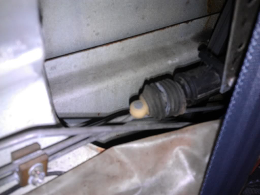
this froze up n i want it out. I just bought the car n never got the remote opener. I'll be fine with the stock lock until the car is back in good shape and i have money to get a proper security system.
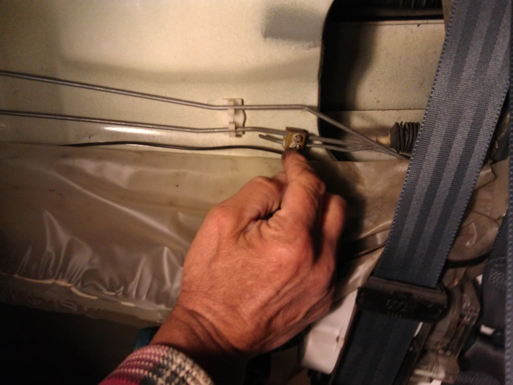
here's a shot from another angle. looks like the installer had the 2 lines twisted. I never looked at the other side for comparison. Sorry to jack the thread but you all seem concerned with keeping cars in the person who owns them possession & my door won't lock thanks
this froze up n i want it out. I just bought the car n never got the remote opener. I'll be fine with the stock lock until the car is back in good shape and i have money to get a proper security system.
here's a shot from another angle. looks like the installer had the 2 lines twisted. I never looked at the other side for comparison. Sorry to jack the thread but you all seem concerned with keeping cars in the person who owns them possession & my door won't lock
thanks
 06-03-2012, 10:04 AM
#21
Thanks for taking the time to do this. However, I have a couple recommendations. Your actuator is working at a wicked angle! You want it mounted horizontally, in-line as much as possible with the lock rod. It will last longer and not have to work as hard. Also, there is a better spot with a hole near the door mounted belt...on the crx at least. There you can use the simple bracket that comes with the actuator. Lastly, the trunk/hatch/boot release is easy to do. Here is mine installed:

06-03-2012, 03:00 PM
#22
Honda-Tech Member
sorry to bump an old one but I need some advice on how to do this in reverse.
this froze up n i want it out. I just bought the car n never got the remote opener. I'll be fine with the stock lock until the car is back in good shape and i have money to get a proper security system.
here's a shot from another angle. looks like the installer had the 2 lines twisted. I never looked at the other side for comparison. Sorry to jack the thread but you all seem concerned with keeping cars in the person who owns them possession & my door won't lock thanks
this froze up n i want it out. I just bought the car n never got the remote opener. I'll be fine with the stock lock until the car is back in good shape and i have money to get a proper security system.
here's a shot from another angle. looks like the installer had the 2 lines twisted. I never looked at the other side for comparison. Sorry to jack the thread but you all seem concerned with keeping cars in the person who owns them possession & my door won't lock
thanks
06-03-2012, 03:54 PM
#23
Honda-Tech Member
Join Date: Jun 2012
Posts: 28
Likes: 0
Received 0 Likes
on
0 Posts
I did, just 1 wire i couldn't figure out where it went. Car starts so i don't care. The whole system was out. we kept pulling and found a pretty decent alarm in there. Had a shake sensor and everything. Passenger door locks now tho. I'm happy. Now my concern has shifted to fixing the rust in the spare tire area. I can see the top of my muffler and the driveway under the car. I'll make another thread when i'm getting ready to tackle that. Next job on my list is getting the new clutch, flywheel, shift stabilizer, ball joints, tie rod ends, and rear main seal into the car. 
06-04-2012, 12:10 AM
#24
B*a*n*n*e*d

Join Date: Sep 2011
Location: fbgdd > htgdd
Posts: 283
Likes: 0
Received 0 Likes
on
0 Posts
aftermarket actuator are loud and violent.. do yourself a favor and hit up a junkyard for an ef with power door locks factory. they're built into the latch assembly and come out really easy. they have two wires coming from them that you can wire up just like the aftermarket actuators, and you don't have to worry about finding a good spot to mount them
11-02-2012, 03:50 PM
#25
Honda-Tech Member
Join Date: Mar 2005
Location: Seattle, WA
Posts: 1,260
Likes: 0
Received 0 Likes
on
0 Posts
I've wired up a friends Integra using the 2 relay diagram, I keep blowing the battery fuse in the fuse box. Any suggestions? I've checked the wires several times, everything is wired correctly. I'm guessing its my ground but its at a stock ground location behind the drivers kick panel.

