
Confused on my Swap
 11-19-2013, 06:53 AM
#1
I can say from experience that searching will help you but a lot of the time it may just sound confusing unless you get down and start doing it yourself. You end up realizing what people are talking about as you are doing it. Looking at it from a distance and trying to grasp it all can be very hard.
I just want to start by saying I've gotten a lot of PMs lately asking me questions. Just start a thread. I frequent this forum multiple times a day and if I have an answer, or I can find an answer, I will post it.
As for this question. The 1.5 to 1.6L Honda swap for our cars is quite easy. I am going to lay it out the easiest I can, call this a quick write up and discussion for those who are confused and PMing me.
The 1.5L in question is most likely a D15B1 or similar motor. These are SOHC, non-VTEC, DPFI, OBD0 motors.
The 1.6L is most likely the D16A6 from the SI or it could be a later model D16Z6/D16Y8 which will require VTEC wiring.
First things first. You need to install the actual motor into the car. Very easy and straight forward. The transmission from your current motor will fit the new motor. The clutch should match the transmission. The flywheel should match the motor. The motor mounts are very straight forward since it is a D-series. You should be able to use the motor mount on the motor or use the old one from your current motor and swap it over. Most everything else fits.
Now comes the harder part for many. The wiring. It is very easy to do the wiring. You use the stock motor wiring harness from your car. I had a D15B1 in my car. I took the motor harness off of that motor and swapped it over to my new motor. The motor you buy may have a harness, you do not use this harness. You can take some of the plugs and use them, but the actual harness is not used. This is because the large white plugs on the shock tower do not match up and you cannot plug and play the new harness.
With that in mind, you need to convert from DPFI to MPFI. This is very easy.
DPFI to MPFI
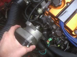
The dual point fuel injection found on some of the EF D series motors is made for fuel efficiency. With that said, they are basically a glorified carburetor. Replacing the DPFI intake manifold with a MPFI intake manifold will increase performance even as a standalone modification. It is very easy to wire. Make sure to label wires. It is also a good idea to run them through a plug instead of direct wiring them to the ECU. That way you can disconnect the plug if you remove the motor again, instead of cutting wires.
Shopping List
1. Four injector Plugs
2. Injector Resister box (if applicable)
3. One �A� Male ECU plug and one �B� or �C� Male ECU plug
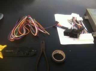
4. Assorted colored Wire
5. Soldering equipment, crimping equipment, or anything applicable.
6. Heat shrink, electrical tape or liquid tape
7. Wire wrap (black plastic, about $1 per ft, OEM style wire covering)
Installation
1. If you have peak and hold injectors, you will need to install an injector resister box. I suggest the driver side shock tower mounting area.
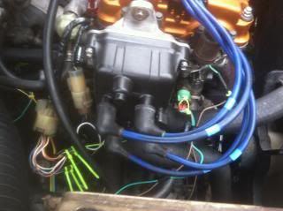
2. The MPFI distributor should have a 7 pin plug instead of the 5 pin plug on the DPFI distributor. This means chopping off the existing plug on the engine harness and replacing it with a new plug.
3. There should be 2 wires that are not connected to the existing engine harness. These should be extended into the cabin through a small bushing near the, passenger side, rear transmission mount.
4. The injector plugs from the DPFI won�t fit the injectors on the new motor, so you will have to source 4 new plugs.
5. Remove the DPFI plug from the wires. You should be left with yellow and a yellow/black wire on one plug and a red and yellow/black wire on the other plug.
6. Connect both of the yellow/black wires together and run them to the yellow/black wire on the injector resister box. If you don�t have an injector resister box, I believe you run the wires to each injector�s red/black wire.
7. Take the yellow wire from the old DPFI plug and run it to cylinder #1
8. Take the red wire from the old DPFI plug and run it to cylinder #3
9. Run the wires from cylinder #2 and #4 into the cabin.
10. Wiring the ECU comes next, here are the pin outs for everything you have extended into the cabin
A3 - #2 Injector
A7 - #4 Injector
B10 � Move wire from C1 to here
B12 � Move wire from C2 to here
C1 � Blue/Green Distributor
C2 � Blue/Yellow Distributor
11. Test that the MPFI wiring is correct. Car should start, timing may be off if the distributor was changed.
12. Wrap all connections with appropriate tape and wrap in black plastic to give it a stock, OEM, look.
After you have added the MPFI wiring to your existing wiring harness, you may need to convert to OBD1. The D16A6 is OBD0, the VTEC D16 motors are OBD1.
If images are too small: click images, click magnifying glass, click magnifying glass again to view original size.
I did my own OBD0 to OBD1 conversion this weekend and thought I would share it with everyone to hopefully prevent some repeat threads. The whole process is actually very easy and shouldn't take much time at all. If you are prepared, I would say it should take you 1-2 hours depending on your choices and skill.
What you need:
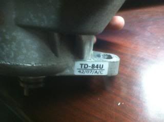
1. OBD1 Distributor for your model of motor (D,B,H, ect) mine was a B16A.
2. A conversion or 'jumper' harness. I bought this one on eBay for $43. 2 Day shipping and every wire was perfect. (I checked the pinouts myself)
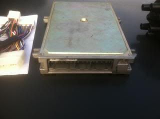
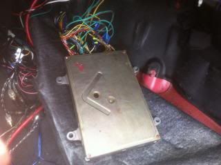
3. An OBD1 ECU. I chose the P28. The P30, P72, ect will all work. Note that if you have a VTEC motor and you chose a non-VTEC ECU, it will need additional work for it to work. For this write up I am assuming you already have an ECU that will work with your motor.
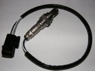
4. A 4-wire oxygen sensor. I had one on my car already.
Now that you have everything, it's time install it.
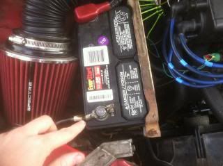
1. First things first, disconnect the negative cable from the battery to prevent injuring yourself or causing damage.
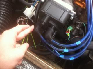
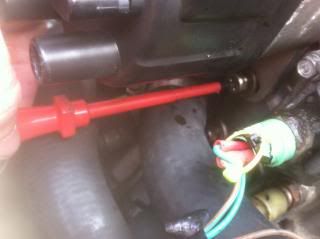
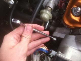
2. Remove your old distributor. You must remove the spark plug wires. Then there are 3 bolts and 2 plugs.
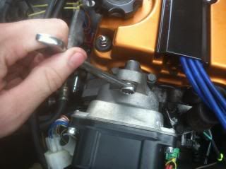
3. Install your new OBD1 distributor. You can see in the photo that I removed the OBD1 plugs on my distributor and soldered on OBD0 plugs so it will plug into my existing motor harness. You can do this, or solder OBD1 plugs on your motor harness. Or you can get a jumper harness for this too.
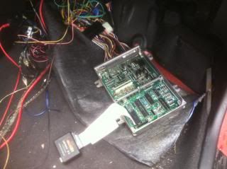
4. Now onto the interesting stuff. Go inside and unplug your OBD0 ECU.
5. Plug in your conversion harness to the existing plugs.
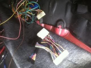
6. You should have a set of wires that plugs into your conversion harness. This subharness is for additional sensors that were not present on OBD0 vehicles.
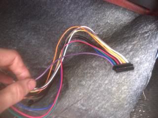
This is the pinouts for the subharness that was included with my conversion harness.
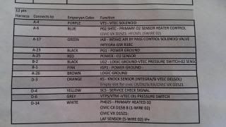
7. No pictures for the next couple of steps. But there should be a wire on the subharness designated for pulling ECU codes. You should wire this to one end of a switch. On the other end of the switch, attach a ground. When you have a check engine light pop up, you can flip the switch and the check engine light will blink in the same manner as the OBD0 ECU LED. You can tuck this switch up somewhere or mount it some where out of the way. You shouldn't have to use it often.
8. Wire your new 4-wire O2 sensor. Two of the wires are for the heater. One is a ground. The last one is the signal wire.
9. Wiring VTEC if your motor has it. One wire will go to the solenoid. Another wire will go to the pressure switch. The other side of the pressure switch will go to a known good ground. I recommend the thermostat housing.
10. If your ECU has a knock board you can wire the knock sensor. If it does not, do not wire the knock sensor. My P28 did not have a knock board so I did not wire my knock sensor to it.
11. Plug in your ECU and connect the subharness to the conversion harness.
You're done! Very simple to do.
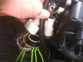
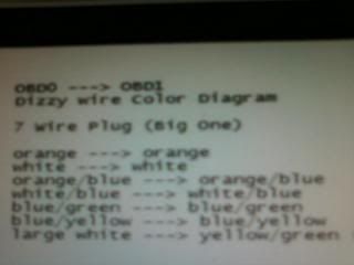
If you have to swap plugs on your distributor or motor harness, it is very easy to do. You color match for the most part. If you swap the plugs on the motor harness, the large white wire on the OBD0 7-pin plug will be a yellow/green wire on the OBD1 7-pin plug. The same goes for swapping the plug on the distributor, but the opposite. This large white wire and yellow/green wire are by themselves on the plug. They do not have another wire above or below them.
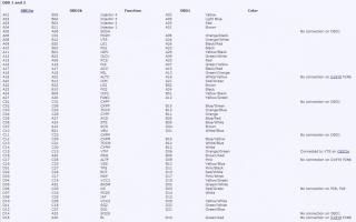
Here are the OBD0 pinouts:
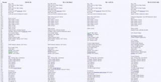
Here are the OBD1 pinouts:
Hope this helps. It's been done before but another write up won't hurt when people search for OBD0 to OBD1 conversion.
If you have a VTEC motor, it is easy to add the wires for VTEC.
VTEC � Variable valve timing and electronic lift control
VTEC is a very cool feature available on a wide variety of Honda motors. VTEC is comprised of a solenoid and a pressure switch. When oil pressure reaches a certain pressure, caused by RPM, the switch activates the solenoid. The solenoid pushes oil through part of the head, activating a third lobe portion of the cam. This portion is larger than the normal lobe. The longer travel gives the motor more top end horse power. But it is not optimal at low RPM due to requiring more power to get the cam to spin. So in short, VTEC gives a motor more top end without sacrificing low end HP. Some consider it a gimmick. Many say, �There is no replacement for displacement.� But most people agree VTEC is a good feature that offers a compelling sound and boost to power.
Wiring VTEC
The VTEC wiring is very simple. On a motor with VTEC there is basically two wires to the ECU that need to be added, and a chassis ground.
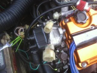
1. Locate the VTEC Solenoid, near the distributor. There should be a single wire coming out of it. Run this to the cabin into A8 on the ECU.
2. Below the Solenoid is the pressure switch. One wire is the signal wire, one is the ground. The signal wire goes to B5 and the ground should be connected to a known good ground. One of the numerous bolts into the frame or even the transmission ground should work.
That is all that is required to wire VTEC. Make sure you have the knock sensor installed and wired also. The knock sensor is not present on D16 VTEC motors.
Originally Posted by longhammer
Hey Freemananana
Is there a write up on swaping from a DX 1.5 to the SI 1.6 step by step ? I looked but could not find what I was needing, the electrical work is rather confusing, Im not sure what to do with the stock DX Harness to Modify it to Fit the SI engine harness?
I know this is anoying but I dont want to mess this up any help or knowledge would really be appreciated, all the write ups show the re wiring for the doing the DPFI to MPFI which I get but the the plugs are confusing the crap outta me
As for this question. The 1.5 to 1.6L Honda swap for our cars is quite easy. I am going to lay it out the easiest I can, call this a quick write up and discussion for those who are confused and PMing me.
The 1.5L in question is most likely a D15B1 or similar motor. These are SOHC, non-VTEC, DPFI, OBD0 motors.
The 1.6L is most likely the D16A6 from the SI or it could be a later model D16Z6/D16Y8 which will require VTEC wiring.
First things first. You need to install the actual motor into the car. Very easy and straight forward. The transmission from your current motor will fit the new motor. The clutch should match the transmission. The flywheel should match the motor. The motor mounts are very straight forward since it is a D-series. You should be able to use the motor mount on the motor or use the old one from your current motor and swap it over. Most everything else fits.
Now comes the harder part for many. The wiring. It is very easy to do the wiring. You use the stock motor wiring harness from your car. I had a D15B1 in my car. I took the motor harness off of that motor and swapped it over to my new motor. The motor you buy may have a harness, you do not use this harness. You can take some of the plugs and use them, but the actual harness is not used. This is because the large white plugs on the shock tower do not match up and you cannot plug and play the new harness.
With that in mind, you need to convert from DPFI to MPFI. This is very easy.
DPFI to MPFI
The dual point fuel injection found on some of the EF D series motors is made for fuel efficiency. With that said, they are basically a glorified carburetor. Replacing the DPFI intake manifold with a MPFI intake manifold will increase performance even as a standalone modification. It is very easy to wire. Make sure to label wires. It is also a good idea to run them through a plug instead of direct wiring them to the ECU. That way you can disconnect the plug if you remove the motor again, instead of cutting wires.
Shopping List
1. Four injector Plugs
2. Injector Resister box (if applicable)
3. One �A� Male ECU plug and one �B� or �C� Male ECU plug
4. Assorted colored Wire
5. Soldering equipment, crimping equipment, or anything applicable.
6. Heat shrink, electrical tape or liquid tape
7. Wire wrap (black plastic, about $1 per ft, OEM style wire covering)
Installation
1. If you have peak and hold injectors, you will need to install an injector resister box. I suggest the driver side shock tower mounting area.
2. The MPFI distributor should have a 7 pin plug instead of the 5 pin plug on the DPFI distributor. This means chopping off the existing plug on the engine harness and replacing it with a new plug.
3. There should be 2 wires that are not connected to the existing engine harness. These should be extended into the cabin through a small bushing near the, passenger side, rear transmission mount.
4. The injector plugs from the DPFI won�t fit the injectors on the new motor, so you will have to source 4 new plugs.
5. Remove the DPFI plug from the wires. You should be left with yellow and a yellow/black wire on one plug and a red and yellow/black wire on the other plug.
6. Connect both of the yellow/black wires together and run them to the yellow/black wire on the injector resister box. If you don�t have an injector resister box, I believe you run the wires to each injector�s red/black wire.
7. Take the yellow wire from the old DPFI plug and run it to cylinder #1
8. Take the red wire from the old DPFI plug and run it to cylinder #3
9. Run the wires from cylinder #2 and #4 into the cabin.
10. Wiring the ECU comes next, here are the pin outs for everything you have extended into the cabin
A3 - #2 Injector
A7 - #4 Injector
B10 � Move wire from C1 to here
B12 � Move wire from C2 to here
C1 � Blue/Green Distributor
C2 � Blue/Yellow Distributor
11. Test that the MPFI wiring is correct. Car should start, timing may be off if the distributor was changed.
12. Wrap all connections with appropriate tape and wrap in black plastic to give it a stock, OEM, look.
After you have added the MPFI wiring to your existing wiring harness, you may need to convert to OBD1. The D16A6 is OBD0, the VTEC D16 motors are OBD1.
If images are too small: click images, click magnifying glass, click magnifying glass again to view original size.
I did my own OBD0 to OBD1 conversion this weekend and thought I would share it with everyone to hopefully prevent some repeat threads. The whole process is actually very easy and shouldn't take much time at all. If you are prepared, I would say it should take you 1-2 hours depending on your choices and skill.
What you need:
1. OBD1 Distributor for your model of motor (D,B,H, ect) mine was a B16A.

2. A conversion or 'jumper' harness. I bought this one on eBay for $43. 2 Day shipping and every wire was perfect. (I checked the pinouts myself)

3. An OBD1 ECU. I chose the P28. The P30, P72, ect will all work. Note that if you have a VTEC motor and you chose a non-VTEC ECU, it will need additional work for it to work. For this write up I am assuming you already have an ECU that will work with your motor.

4. A 4-wire oxygen sensor. I had one on my car already.

Now that you have everything, it's time install it.
1. First things first, disconnect the negative cable from the battery to prevent injuring yourself or causing damage.

2. Remove your old distributor. You must remove the spark plug wires. Then there are 3 bolts and 2 plugs.


3. Install your new OBD1 distributor. You can see in the photo that I removed the OBD1 plugs on my distributor and soldered on OBD0 plugs so it will plug into my existing motor harness. You can do this, or solder OBD1 plugs on your motor harness. Or you can get a jumper harness for this too.


4. Now onto the interesting stuff. Go inside and unplug your OBD0 ECU.

5. Plug in your conversion harness to the existing plugs.

6. You should have a set of wires that plugs into your conversion harness. This subharness is for additional sensors that were not present on OBD0 vehicles.

This is the pinouts for the subharness that was included with my conversion harness.

7. No pictures for the next couple of steps. But there should be a wire on the subharness designated for pulling ECU codes. You should wire this to one end of a switch. On the other end of the switch, attach a ground. When you have a check engine light pop up, you can flip the switch and the check engine light will blink in the same manner as the OBD0 ECU LED. You can tuck this switch up somewhere or mount it some where out of the way. You shouldn't have to use it often.
8. Wire your new 4-wire O2 sensor. Two of the wires are for the heater. One is a ground. The last one is the signal wire.
9. Wiring VTEC if your motor has it. One wire will go to the solenoid. Another wire will go to the pressure switch. The other side of the pressure switch will go to a known good ground. I recommend the thermostat housing.
10. If your ECU has a knock board you can wire the knock sensor. If it does not, do not wire the knock sensor. My P28 did not have a knock board so I did not wire my knock sensor to it.
11. Plug in your ECU and connect the subharness to the conversion harness.

You're done! Very simple to do.
If you have to swap plugs on your distributor or motor harness, it is very easy to do. You color match for the most part. If you swap the plugs on the motor harness, the large white wire on the OBD0 7-pin plug will be a yellow/green wire on the OBD1 7-pin plug. The same goes for swapping the plug on the distributor, but the opposite. This large white wire and yellow/green wire are by themselves on the plug. They do not have another wire above or below them.

Here are the OBD0 pinouts:

Here are the OBD1 pinouts:

Hope this helps. It's been done before but another write up won't hurt when people search for OBD0 to OBD1 conversion.
If you have a VTEC motor, it is easy to add the wires for VTEC.
VTEC � Variable valve timing and electronic lift control
VTEC is a very cool feature available on a wide variety of Honda motors. VTEC is comprised of a solenoid and a pressure switch. When oil pressure reaches a certain pressure, caused by RPM, the switch activates the solenoid. The solenoid pushes oil through part of the head, activating a third lobe portion of the cam. This portion is larger than the normal lobe. The longer travel gives the motor more top end horse power. But it is not optimal at low RPM due to requiring more power to get the cam to spin. So in short, VTEC gives a motor more top end without sacrificing low end HP. Some consider it a gimmick. Many say, �There is no replacement for displacement.� But most people agree VTEC is a good feature that offers a compelling sound and boost to power.
Wiring VTEC
The VTEC wiring is very simple. On a motor with VTEC there is basically two wires to the ECU that need to be added, and a chassis ground.
1. Locate the VTEC Solenoid, near the distributor. There should be a single wire coming out of it. Run this to the cabin into A8 on the ECU.
2. Below the Solenoid is the pressure switch. One wire is the signal wire, one is the ground. The signal wire goes to B5 and the ground should be connected to a known good ground. One of the numerous bolts into the frame or even the transmission ground should work.
That is all that is required to wire VTEC. Make sure you have the knock sensor installed and wired also. The knock sensor is not present on D16 VTEC motors.
 11-19-2013, 07:26 AM
#2
Honda-Tech Member

Join Date: Oct 2013
Posts: 27
Likes: 0
Received 0 Likes
on
0 Posts
awesome so when you say u do not use the harness are we speaking about the harness on the motor or the one from the DX ? the new engine has the SI Harness on it obviously so is it that one I do not use?
11-19-2013, 08:43 AM
#5
There are a couple wires on the SI harness you will want. Take the distributor plug wires and injector wires from that harness. Cut them off the Si harness and solder them onto the DX harness. The distributor plugs will replace the plugs on your stock harness so that the Si distributor will plug into them.
You will take the injector plugs from your Si harness and wire them into the harness from your stock motor.

Thread
Thread Starter
Forum
Replies
Last Post