
I need help diagnosing power lock issue 96 civic hx
 01-23-2015, 09:42 PM
#26
Honda-Tech Member
Thread Starter
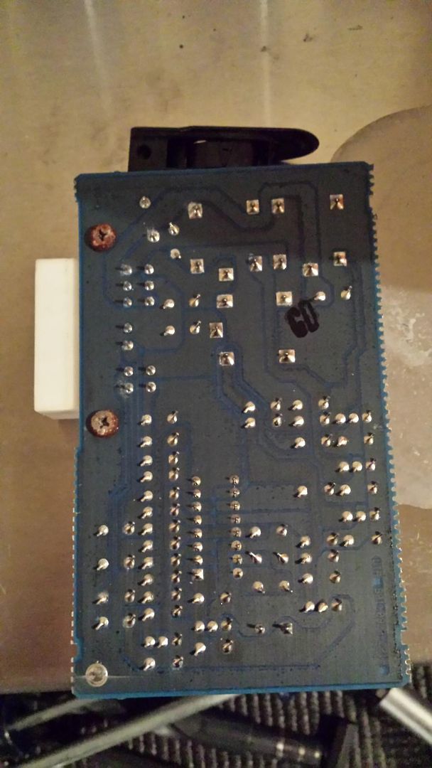
Playing with the board for the control module I found lots of corrosion. I cleaned the bolts holding the plug and the soldered joints on the board itself. I could get 12v at the white ggreen plug solder point to the board and the next junction took it down to 2v and every other power after that reading was 2v. Cleaning the connection I could get it back to 12v at the second joint and try to unlock and the board would make an audible click and then only read 2v.
Yes it's a bad board but now my wHite green wire is back down to 9v at the plug. Car batt is still 12v.
Tomorrow I play with the but connectors or just give up at this point
Yes it's a bad board but now my wHite green wire is back down to 9v at the plug. Car batt is still 12v.
Tomorrow I play with the but connectors or just give up at this point

 01-24-2015, 06:10 AM
#27
Honda-Tech Member
Thread Starter
I found a club eg post about a similar issue and the user was able to re solder the board to make it functional. The corrosion had just eaten the connection
So I can verify operation by supplying a known good power source to the white green pin
my blue/white wire is reading 5 volts from the pin at the connector for the module, this happens with the door closed and with it open, with key in ignition turned to on and with it off. So a constant 5v
Night off so just a hot link for circuit board repair
Here's a D.I.Y Repair & Preventative maintenance writeup for the ICU (Integrated control unit) box located under your dash in the fuse box.
The ICU controls many circuits such as:
- turn on dome light
- turn signals
- seatbelt switch
- ignition switch
- e0brake down switch
- door ajar beeper
- rear window defogger timer
- controls windshield wiper intermittent
- park functions
- some dash warning lights
As our cars become really old, these circuits are failure prone and it's easy to go over all possible causes.
The real cause for this is a buildup of heat and cold solder joints.
The ICU modules are no longer available new from the Honda dealer, so wreckers or repair is your only choice.
1. Locate the ICU under dash in behind fuse box. Remove the ICU. You need a 10 mm wrench and a 10 mm deep socket. There are two 10 mm bolts holding the fuse box on, remove them. You can now twist the fuse box so that you can remove the ICU.
**Now would be a good time to check all your fuses and reseat all connectors you see**

2. With the ICU removed , gently pry the tabs on the sides so the two pieces can seperate. You should see the circuit board inside. Carefully inspect the component side for bulging capacitors and anything burnt. Turn it over and inspect the solder side of the board, you are looking for burnt traces (the green copper lines) , cold solder joints , and burnt spots.


3. If you dont have any burnt traces or bad components you can attempt to fix the ICU. Minus burnt components and burnt traces, the only other thing to look for is a "cold solder" joint. These are solder joints that due to age and vibration, have cracked causing intermittent connections. You can fix these by warming up a 15 - 30 watt soldering iron and placing it on the solder joint and adding a TINY bit of rosin core 60/40 electronics solder. Be careful here you can burn components and lift traces if your not careful.
4. Once you have decided whether to replace the ICU or to repair it I sugest "bullet proofing" it. To make your ICU last another 20 years you should follow these steps.
5. Heat up and add new solder to the header pins on the board. These are the pins that the connectors connect to and subsequently take the most stress and vibrations. Header pins and connectors are usually the weakest link of any vintage electrical system.


6. After you have resoldered the header pins, you need to get them looking new and free of any corrosion. A red 3m/scotchbrite pad works wonders for this. Gently clean both sides of the header pins with this pad. Don't do it too much tho otherwise you will take off too much metal (making the pin smaller) and cause the female pin to not make 100% contact with the male pin.

7. After soldering and cleaning the header pins, you want to eliminate heat buildup in this unit as much as possible. Find the resistor network at RM1 (or about 1/4" below the female connector on the component side). Being tightly packed resistors surrounded by plastic these tend to get hot and melt their own solder joints. You want to have vents above this, and the relay at RY1 (left of said female connector , large square black box).

8. You are going to drill several vent holes above the two main heat producing units on this board. This is the easy part. Put the board back in the case without snapping it shut, now take a marker and mark several holes above the relay and above the resistor network.
9. Remove the half of the case that you just drew the drill template on and drill the holes. Make sure to blow out any plastic shavings left behind from this process.


10. Put the board back in the half with the label , and now snap the drilled half on top.

10. Remove negative battery cable, and re attach the ICU to the fuse box. Connect battery and see that everything works.
The ICU controls many circuits such as:
- turn on dome light
- turn signals
- seatbelt switch
- ignition switch
- e0brake down switch
- door ajar beeper
- rear window defogger timer
- controls windshield wiper intermittent
- park functions
- some dash warning lights
As our cars become really old, these circuits are failure prone and it's easy to go over all possible causes.
The real cause for this is a buildup of heat and cold solder joints.
The ICU modules are no longer available new from the Honda dealer, so wreckers or repair is your only choice.
1. Locate the ICU under dash in behind fuse box. Remove the ICU. You need a 10 mm wrench and a 10 mm deep socket. There are two 10 mm bolts holding the fuse box on, remove them. You can now twist the fuse box so that you can remove the ICU.
**Now would be a good time to check all your fuses and reseat all connectors you see**
2. With the ICU removed , gently pry the tabs on the sides so the two pieces can seperate. You should see the circuit board inside. Carefully inspect the component side for bulging capacitors and anything burnt. Turn it over and inspect the solder side of the board, you are looking for burnt traces (the green copper lines) , cold solder joints , and burnt spots.
3. If you dont have any burnt traces or bad components you can attempt to fix the ICU. Minus burnt components and burnt traces, the only other thing to look for is a "cold solder" joint. These are solder joints that due to age and vibration, have cracked causing intermittent connections. You can fix these by warming up a 15 - 30 watt soldering iron and placing it on the solder joint and adding a TINY bit of rosin core 60/40 electronics solder. Be careful here you can burn components and lift traces if your not careful.
4. Once you have decided whether to replace the ICU or to repair it I sugest "bullet proofing" it. To make your ICU last another 20 years you should follow these steps.
5. Heat up and add new solder to the header pins on the board. These are the pins that the connectors connect to and subsequently take the most stress and vibrations. Header pins and connectors are usually the weakest link of any vintage electrical system.
6. After you have resoldered the header pins, you need to get them looking new and free of any corrosion. A red 3m/scotchbrite pad works wonders for this. Gently clean both sides of the header pins with this pad. Don't do it too much tho otherwise you will take off too much metal (making the pin smaller) and cause the female pin to not make 100% contact with the male pin.
7. After soldering and cleaning the header pins, you want to eliminate heat buildup in this unit as much as possible. Find the resistor network at RM1 (or about 1/4" below the female connector on the component side). Being tightly packed resistors surrounded by plastic these tend to get hot and melt their own solder joints. You want to have vents above this, and the relay at RY1 (left of said female connector , large square black box).
8. You are going to drill several vent holes above the two main heat producing units on this board. This is the easy part. Put the board back in the case without snapping it shut, now take a marker and mark several holes above the relay and above the resistor network.
9. Remove the half of the case that you just drew the drill template on and drill the holes. Make sure to blow out any plastic shavings left behind from this process.
10. Put the board back in the half with the label , and now snap the drilled half on top.
10. Remove negative battery cable, and re attach the ICU to the fuse box. Connect battery and see that everything works.
Last edited by chrysler kid; 01-24-2015 at 07:11 PM.
01-25-2015, 03:41 PM
#28
Honda-Tech Member
Thread Starter
The green and white wire wound up having a short or a drain
I did end up cleaning the soldering points and the board but the board splits power between the two regulators with a mini relay to trigger the actuators.
Jumping the pins at the module worked because I was only testing one regulator at a time, so the one regulator would function with the drain / short
So a new fused constant power source and everything works again wahoo!

Thread
Thread Starter
Forum
Replies
Last Post
ReneB64
Honda Civic (2006 - 2015)
3
10-06-2017 08:19 AM
Azxster
Audio / Security / Video
4
10-01-2006 06:50 PM
veggiemaster
Audio / Security / Video
3
06-09-2005 10:13 AM