When you click on links to various merchants on this site and make a purchase, this can result in this site earning a commission. Affiliate programs and affiliations include, but are not limited to, the eBay Partner Network.
DIY OE 2-wire to 1-wire horn conversion for EG Civics (using existing relay)
I got a couple really loud horns from a Cadillac at the junkyard a while back and found that I could not simply wire them up to the existing EG Civic horn circuit. First off, the Cadillac horns are single wire, while the OE Honda setup uses two wires. Secondly, the circuits are not the same...
The Honda setup provides CONSTANT power to the horn(s) via the WHT/GRN wire located at the connector for each horn. It's only when the horn button is pushed and the horn relay is activated that ground is provided to the horn circuit via the BLU/RED wire, completing the circuit and blowing the horn.
The problem is that most 1-wire horns are expecting 12v of power ONLY when the relay is activated. They don't need a separate ground wire, because they ground out via the bolt that secures the horn bracket onto the frame.
So what happens when you try to hook up a 1-wire horn to a Honda? Nothing, unless you bolt it to the frame... then it never stops blaring. NEVER. STOPS.
Clearly, the two systems are not the same. This means you have two options: A.) Replace the horn relay with one which is compatible with the 1-wire system, or B.) Modify your existing horn relay, on the cheap... or more specifically, modify your 4-pin relay connector.
Things you will need:
Wire strippers
Phillips screwdriver
Needle nose pliers
Pocket flathead screwdrivers or picks
Electrical tape
2-3 Electrical spade connectors
Small gauge primary wire (optional)
Soldering iron, rosin core solder, & flux OR butt connector (optional)
Shrink tubing (optional)
Time required: 3 beers
Before you do anything, disconnect the negative battery cable.
I prefer to start by removing the bumper cover for easy access to the horn connector(s). You can probably get to them by removing the lower deflector and splash guards only, but that seems like a pain.
Remove the 2-pin connector from the OE horn(s) and then snip the wires an inch or two behind the connector. Hang on to the connector, in case you want to switch back to OE horns at some later time.
Unbolt the old horn(s) from the frame and set aside. Bolt the new horns into the frame.
What happens next depends on if your Civic came with one horn or two. My particular Civic came with only one horn on the passenger side. If your car came with both high and low horns from the factory, you will have a second set of WHT/GRN and BLU/RED wires leading to the horn on the driver side. If your car only came with one horn, then you will need to splice into the BLU/RED wire on the passenger side and run some primary wire over to the driver side along the frame. It may also be necessary to splice a few extra inches of primary wire onto the end of the BLU/RED wire so it can easily reach the new horn. I highly recommend braiding, soldering, and shrink tubing any splices you make here. You want something durable since it will be exposed to the elements while driving. You can use butt connectors, but do so at your own risk.
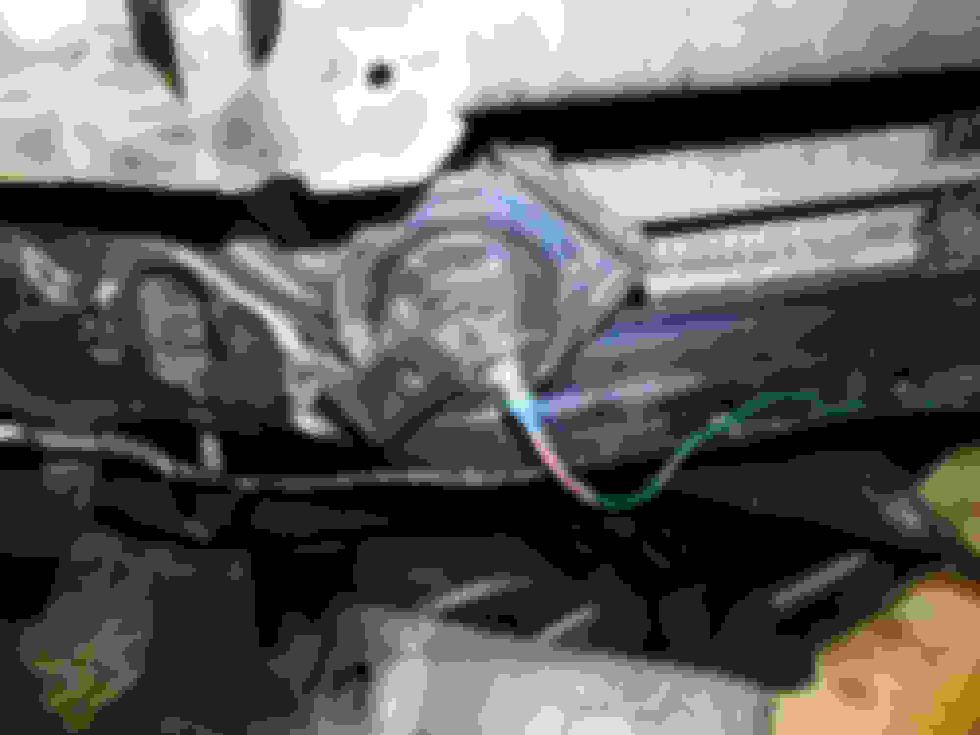
On a side note, as I was searching in vain for the horn wires on the driver side of my car, I came across this BLU/RED wire with a female plug-type connector inside a rubber boot. It's located near the washer fluid motor wire harness. It looks almost as if it's meant for something optional, like a second horn... however, after testing this wire with a multimeter, it appears to be completely unrelated to the horn circuit, despite its color... if anyone can shed any light on this wire, I'm dying to know what it's for.
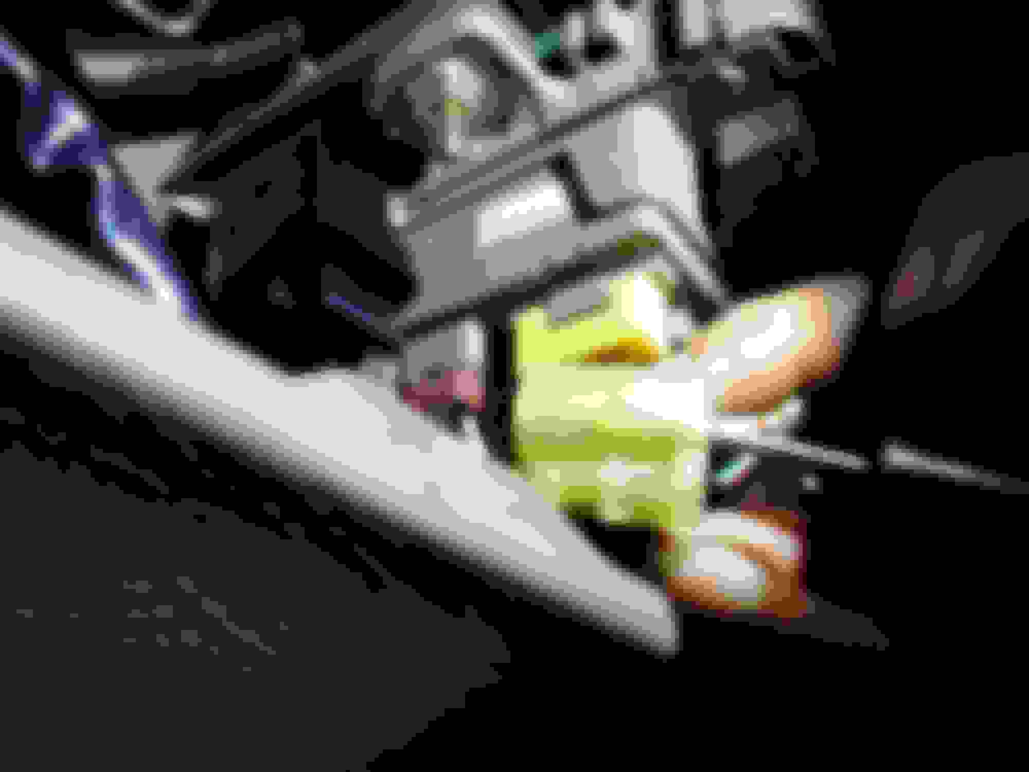
Next, install the spade connector on the end of the BLU/RED wire. If you had to run a wire over to the driver side, then install a spade connector on the end of that wire too. I got a little fancy with the shrink tubing here and made a small protective sleeve for the spade. Then fold the WHT/GRN wire back on itself (it will no longer be needed) and wrap all exposed wires thoroughly with electrical tape. Slide the spade connectors onto the terminal posts on the new horns.
*Now the real fun begins*
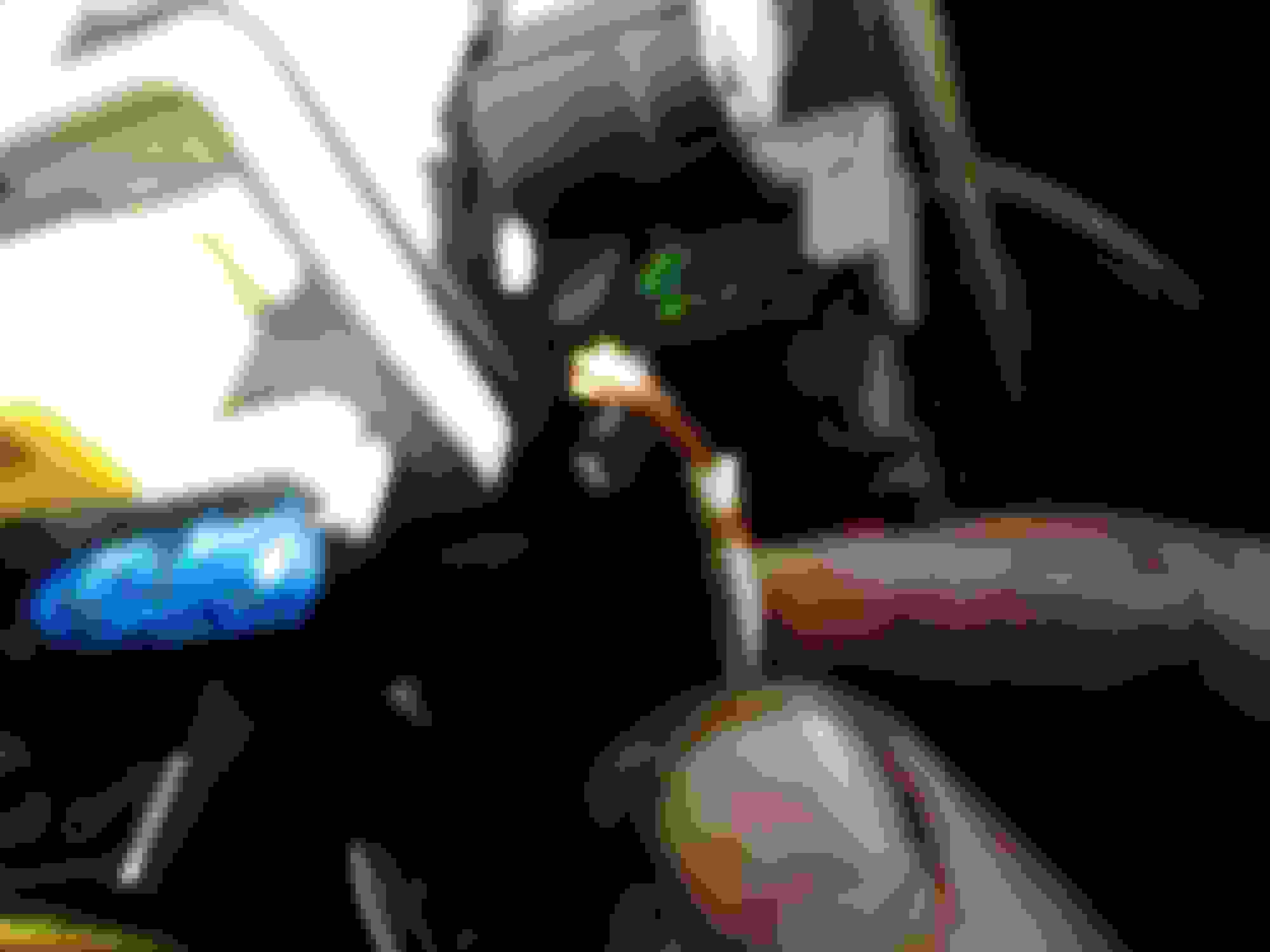
Crawl under the driver side dash and locate your horn relay. It will usually be attached to the right-hand side of the under-dash fuse box. There will be a 4-pin connector with five wires going into it (WHT/GRN, BLU/RED, BLU/GRN, and BLK x2). Slide that connector out of the relay.
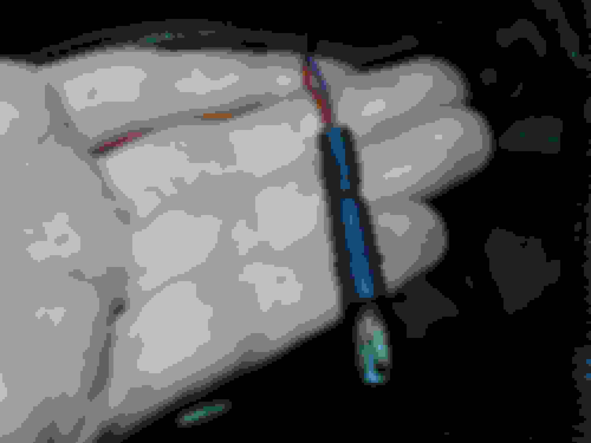
Next, locate the two BLK wires leading into the back of the 4-pin connector. Pare back the plastic tubing/tape, and snip both those wires *AT LEAST* 1.5 inches away from the connector itself. You want to leave some wire behind the connector, because you'll be looping those BLK wires back into the connector later. Strip off the insulation and expose about 3/8" of copper on both BLK wires still attached to the connector.
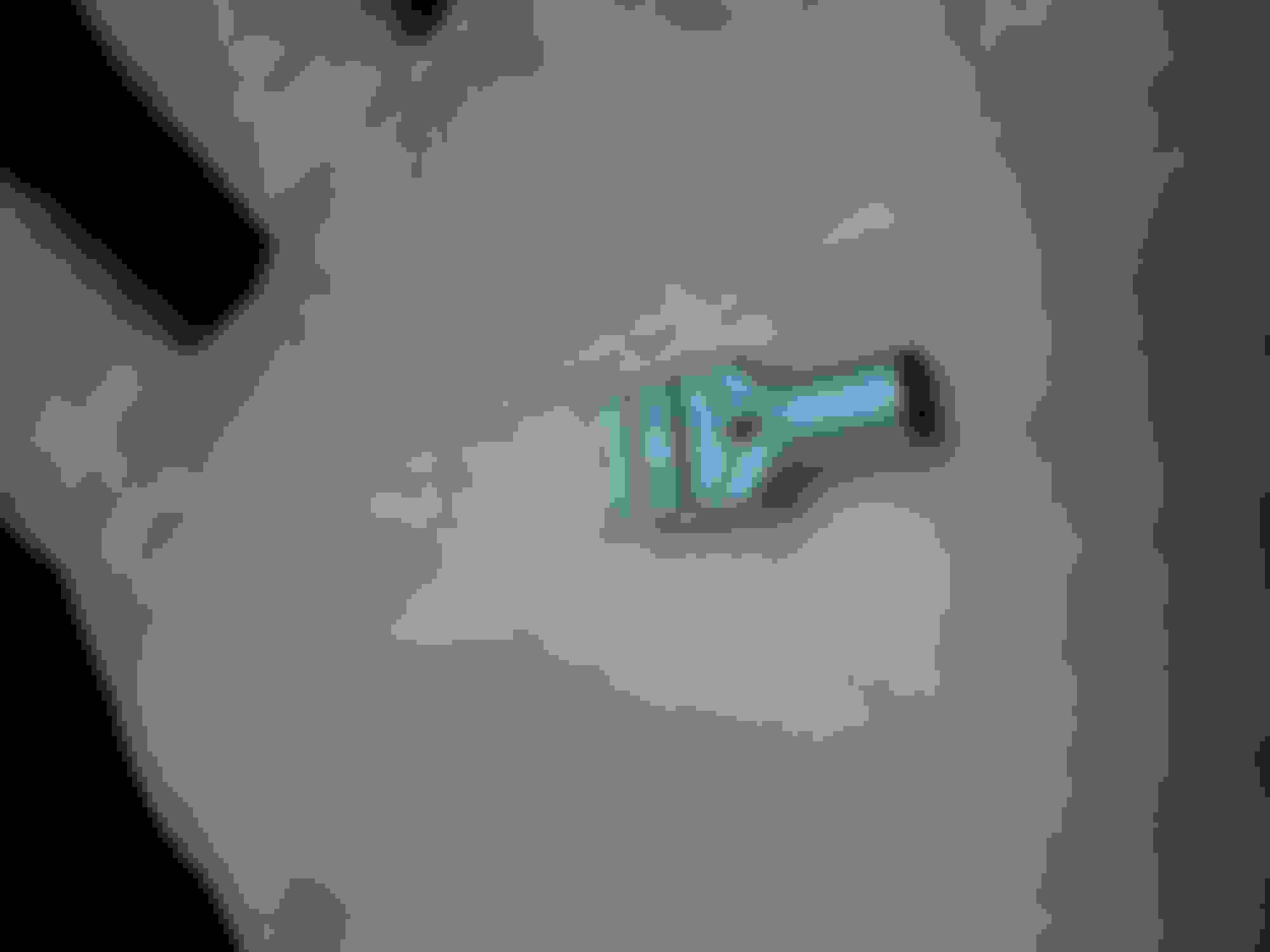
Now take a small pocket flathead or a pick and, going in from the back side of the connector, carefully wedge it between the WHT/GRN wire and the top of the connector housing. Keep pushing until the connector housing bulges slightly and you feel it slip past the tiny plastic retainer holding the internal spade connector in place. Then with a second pick or similar, going in from the front side now, push the spade for the WHT/GRN wire back and out of the connector. Snip the spade off the end of the WHT/GRN wire and toss it, it can't be reused. Expose about 3/8" of copper on the WHT/GRN wire using wire strippers.
Take both BLK wires and the WHT/GRN wire with the exposed copper, braid all three together, and install a new spade on the end. Make sure the spade you use here does not have any additional insulation, as it will need to fit back inside the connector. Gently tug on the spade to make sure all 3 wires are secured properly. Slide the spade back into the connector from the back side.
Fold back the now-unused BLK ground wires leading back towards the wire harness and wrap with electrical tape and cover back up with plastic tubing. Reinstall bumper cover, deflector and splash guards. Reconnect negative battery cable.
Basically, what you've done here is remove ground continuity from the horn circuit (by cutting the two BLK wires), and reused those same wires to supply power to the horn circuit via the WHT/GRN relay power wire. So, now, instead of the BLU/RED wire providing ground continuity at the horns when the button is pressed, it provides 12v battery power. Enjoy your new horns. HONK HONK!
*This procedure MIGHT work on EK Civics 96-00, but I would imagine wire colors will vary. Proceed with caution.
Re: DIY OE 2-wire to 1-wire horn conversion for EG Civics (using existing relay)
Originally Posted by fragmare
I got a couple really loud horns from a Cadillac at the junkyard a while back and found that I could not simply wire them up to the existing EG Civic horn circuit. First off, the Cadillac horns are single wire, while the OE Honda setup uses two wires. Secondly, the circuits are not the same...
The Honda setup provides CONSTANT power to the horn(s) via the WHT/GRN wire located at the connector for each horn. It's only when the horn button is pushed and the horn relay is activated that ground is provided to the horn circuit via the BLU/RED wire, completing the circuit and blowing the horn.
The problem is that most 1-wire horns are expecting 12v of power ONLY when the relay is activated. They don't need a separate ground wire, because they ground out via the bolt that secures the horn bracket onto the frame.
So what happens when you try to hook up a 1-wire horn to a Honda? Nothing, unless you bolt it to the frame... then it never stops blaring. NEVER. STOPS.
Clearly, the two systems are not the same. This means you have two options: A.) Replace the horn relay with one which is compatible with the 1-wire system, or B.) Modify your existing horn relay, on the cheap... or more specifically, modify your 4-pin relay connector.
Hi, this diy is interesting. Thanks for posting it & the pictures!
I have 4 Cadillac horns (notes AFDC respectively) & have them installed on my 93 Civic DX sedan. I tried in vain to install 2 relays rather than using your suggestion, however I cant seem to figure out the appropriate wiring to get them to work w/existing horn button etc. They do work & blow loudly when I apply current to their single wire & have a solid ground to frame!
I like your suggestion & am revisiting your solution although I'm concerned about the current draw of the 4 horns. You only installed 2 horns correct? What's your thought on using the circuit & existing relay for 4 horns? Is it adequate?
Finally, are you merely using a uninsulated spade connector to wire up the 2 black & white/Grn & then pushed it back into its original location in the connector & then pluged it back into the existing horn relay right?

 07-18-2015, 08:48 AM