
mpfi swap help
 11-23-2008, 08:36 PM
#1
Junior Member
Thread Starter
Join Date: Jun 2006
Location: clovis, ca, usa
Posts: 37
Likes: 0
Received 0 Likes
on
0 Posts
ok... it looks alot harder than i though when taking everything apart and rewiring. im stuck now and dont know what else it could be. i have a 91 civic dx. the intake manifold ecu(pm6) and resistor box from a 89 crx si and i used a integra obd0 injectors and harness just for the connectors like the dizzy and injectors. well i wired up everything extended every wire that needed to be extended flipped the wires that need to be flipped depin wires that need to be. after all that i started up the car and it would start and idle fine and also no check engine lights but seems like its not getting enough fuel. it also shuts off after you try revving the motor. so after this i turned on the car again checked the injectors and see if they are working. out of 4 of them only two is working and those two are injector#1 and #3(i believe those are the ones that is wired to the two stock injectors on the dx) cause when you use a long phillps screwdriver and you press it against the injectors you can hear them tapping meaning they are spraying fuel. the ones that are wired direct from the ecu is not working. and this is where im stuck. i checked every single wire all the red/black stripe wire are connected to the resistor, c1 and c2 moved to b10 and b12, added new wires to c1 and c2 connected those to the cps sensor on the dizzy, added wires to a3 and a7 connect those to injectors 2 and 4. did everything. but like i said its only getting fuel to two injectors and not the other. what did i do wrong? what could it be? let me know... help a fellow honda guy out... any help would be appreciated....
 11-23-2008, 11:53 PM
#4
Honda-Tech Member

Join Date: Nov 2008
Location: san diego CA
Posts: 26
Likes: 0
Received 0 Likes
on
0 Posts
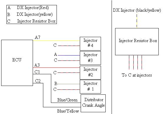
you have to run the two stock injector power wires, i think they are yellow and black,to power the resister box then run the other two wires to the right injectors, the other two injectors get wires from the ecu, all four injector grounds go to the resistor box. good luck
11-24-2008, 12:08 AM
#5
Honda-Tech Member
the injectors you have now are fine, thats not your issue.
the injectors do not ground to the resistor box.. thats where they get their power. the ecu provides the ground. is the resistor box receiving ecu power from a15? all the injectors should see 12v on one side so check each one. if they all have power you know the res. box is working right. That would lead me to believe the ecu isn't providing a ground to the 2 extra injectors for some reason. make absolutely certain you have the right wires to trigger inj. 2 and 4. perhaps you were just one pin off and tied into the wrong wire. i'd start with that lol.
the injectors do not ground to the resistor box.. thats where they get their power. the ecu provides the ground. is the resistor box receiving ecu power from a15? all the injectors should see 12v on one side so check each one. if they all have power you know the res. box is working right. That would lead me to believe the ecu isn't providing a ground to the 2 extra injectors for some reason. make absolutely certain you have the right wires to trigger inj. 2 and 4. perhaps you were just one pin off and tied into the wrong wire. i'd start with that lol.
11-24-2008, 07:45 AM
#6
Honda-Tech Member
Join Date: Sep 2005
Location: yaktown, usa
Posts: 480
Likes: 0
Received 0 Likes
on
0 Posts
better yet, i know what your problem is. i had the same issue once before. they are right about the 12v source to the resistor box. but you have to have all of injector wired to the resistor box. did you run the two extra injector wires to the resistor box like needed? if not thats where your missing them. they must all run to the resistor box then to the injectors.
11-24-2008, 07:55 AM
#7
Junior Member
Thread Starter
Join Date: Jun 2006
Location: clovis, ca, usa
Posts: 37
Likes: 0
Received 0 Likes
on
0 Posts
ive checked the power to each injector and its giving me a reading of -13dc( i believe thats volts when using a multimeter). also when you move the injector clips from 1 and 3 to injector 2 and 4 those two injectors work but then 1 and 3 doesnt work anymore when you plug 2 and 4 clips into 1 and 3. so i dont know what the hell i did wrong... need this **** to run cuz its my only car....
Trending Topics
11-24-2008, 08:02 AM
#8
Junior Member
Thread Starter
Join Date: Jun 2006
Location: clovis, ca, usa
Posts: 37
Likes: 0
Received 0 Likes
on
0 Posts
11-24-2008, 08:11 AM
#9
Junior Member
Thread Starter
Join Date: Jun 2006
Location: clovis, ca, usa
Posts: 37
Likes: 0
Received 0 Likes
on
0 Posts
what do you mean? i have all the red/black wires going to the same wires that are coming from the resistor box. and the yellow/blk wires from injectors 1 and 3 going to the the yellow/black on the resistor. and the two extra injectors are wired to a3 and a7.... so by what you're saying im lost.....
11-24-2008, 08:14 AM
#10
Honda-Tech Member
Join Date: Sep 2005
Location: yaktown, usa
Posts: 480
Likes: 0
Received 0 Likes
on
0 Posts
this is what i used. sorry i miss stated what i intended to say. i did mean the black/yellow wire to the box. not two wires. ill also check my wiring at home after work(3 more hours to go). i need to start the car anyways. lol, put up for winter, and getting 2+ inches now.
11-24-2008, 01:44 PM
#11
Honda-Tech Member
what do you mean? i have all the red/black wires going to the same wires that are coming from the resistor box. and the yellow/blk wires from injectors 1 and 3 going to the the yellow/black on the resistor. and the two extra injectors are wired to a3 and a7.... so by what you're saying im lost.....
 11-24-2008, 02:18 PM
#12
Honda-Tech Member
Join Date: Sep 2002
Location: colorado springs, co, usa
Posts: 5,643
Likes: 0
Received 28 Likes
on
28 Posts
a little clarification on that diagram - there is no wire directly from the ECU to the injector resistor box on the MPFI car - on the MPFI cars, there is a yellow/black at A13 and a yellow/black at A15 which connect together inside the harness and go to the Main Relay - from the Main Relay, there is a yellow/black to the resistor box - on the DPFI cars, you have the same yellow/black wires from A13 and A15 to the Main Relay and then a yellow/black from the Main Relay which splits into 2 wires going to the main and auxiliary injectors - at least one of those yellow/black injector wires needs to connect to the red at the resistor box - most instructions say tie them together and then connect to the red, but you only need one for the power
11-24-2008, 04:25 PM
#13
Junior Member
Thread Starter
Join Date: Jun 2006
Location: clovis, ca, usa
Posts: 37
Likes: 0
Received 0 Likes
on
0 Posts
okay.. so you dont need the two yellow/black wires to be wired together. only one of them is okay? i will try that out...
well today i was working on it again and i checked all the wiring again and everything is wired correctly so when i went to start the motor it started up fine like it had all injectors running but then when you go to rev the motor up it only goes up to 3k rpms and then it wont go anymore feels like its at redline and also the CEL came on but i couldnt find out what the code was and i couldnt figure out how to trip the CEL to tell me the code. it was like that for like the 1st two starts and then it went back into running only on two injectors for the last 4 tries. so im stuck again.... help me out... and thanks to all that had reply....
well today i was working on it again and i checked all the wiring again and everything is wired correctly so when i went to start the motor it started up fine like it had all injectors running but then when you go to rev the motor up it only goes up to 3k rpms and then it wont go anymore feels like its at redline and also the CEL came on but i couldnt find out what the code was and i couldnt figure out how to trip the CEL to tell me the code. it was like that for like the 1st two starts and then it went back into running only on two injectors for the last 4 tries. so im stuck again.... help me out... and thanks to all that had reply....
11-24-2008, 04:30 PM
#14
Junior Member
Thread Starter
Join Date: Jun 2006
Location: clovis, ca, usa
Posts: 37
Likes: 0
Received 0 Likes
on
0 Posts
arent the wires from the resistor box(male end) red/black with one that is yellow/black ? and on the female end is all black and one red ? is that correct ?
11-24-2008, 04:33 PM
#15
Junior Member
Thread Starter
Join Date: Jun 2006
Location: clovis, ca, usa
Posts: 37
Likes: 0
Received 0 Likes
on
0 Posts
so tying up those two yellow/black wire and then wiring up to the yellow/blk on resistor box messes up the ground/power? is that why the other two injectors arent working?
11-24-2008, 08:45 PM
#17
Junior Member
Thread Starter
Join Date: Jun 2006
Location: clovis, ca, usa
Posts: 37
Likes: 0
Received 0 Likes
on
0 Posts
ok... ill try that out.... and any clue on why the car wont rev past 3k rpms ? i switch the outside wires on the tps sensor... so i dont know what else... ??????
11-24-2008, 10:00 PM
#18
Honda-Tech Member
iTrader: (1)
Join Date: Jun 2008
Location: clarksville, tn, usa
Posts: 443
Likes: 0
Received 0 Likes
on
0 Posts
sounds like ur in limp mode to me. the computer knows something is wrong and wont let you rev up too high. find out what codes ur tripping and then you should know why your in limp mode. you could just get obd1 injectors and clips and get rid of the resistor box completely.
11-25-2008, 06:27 AM
#19
Honda-Tech Member
Join Date: Sep 2002
Location: colorado springs, co, usa
Posts: 5,643
Likes: 0
Received 28 Likes
on
28 Posts
just look at the LED on the ECU and count the number of times it flashes for the code - unless you reset the ECU, the codes are stored there and will show up even if the CEL is not on - what distributor is in it?
11-25-2008, 07:58 AM
#20
Honda-Tech Member
Join Date: Sep 2005
Location: yaktown, usa
Posts: 480
Likes: 0
Received 0 Likes
on
0 Posts
you could also have a bad tps and iat sensor. both mine were bad making my car get stuck in limp mode as well. which is what you car is doing(stuck under 3k rev limit).
11-25-2008, 06:54 PM
#21
Junior Member
Thread Starter
Join Date: Jun 2006
Location: clovis, ca, usa
Posts: 37
Likes: 0
Received 0 Likes
on
0 Posts
11-25-2008, 09:20 PM
#22
Honda-Tech Member
if you do want to use obd1 injectors for other reasons though you can swap them right in to your stock intake manifold. i believe you can alter the obd0 clips to work with the obd1 injectors but i have not done this personally. when i converted mine over i had the harness from my donor car so i just ganked the obd1 clips off of there. Then all you have to do is remove the resistor box and solder the 5 wires in the harness that went to it together. Their are 4 red/black wires, and 1 yellow/black wire.
11-25-2008, 11:35 PM
#23
Honda-Tech Member
Join Date: Nov 2008
Location: san diego CA
Posts: 26
Likes: 0
Received 0 Likes
on
0 Posts
i would say the no rev past 3k is from the dizzy, thats where all the sensors are that controll and comunicate spark
11-25-2008, 11:41 PM
#24
Honda-Tech Member
Join Date: Jul 2007
Location: Veridian city.
Posts: 740
Likes: 0
Received 0 Likes
on
0 Posts
11-26-2008, 02:42 AM
#25
Honda-Tech Member
Join Date: Sep 2005
Location: yaktown, usa
Posts: 480
Likes: 0
Received 0 Likes
on
0 Posts
i agree, because if something were to fail the car would either not run, or run like complete crap.a majority of the time the car just stops running. and i dont think you can get a "cel" on you engine warning light from an obd0 car. he just has to check at the ecu for the codes. also, it could be a bad map sensor. how did you go about hooking your one on the firewall up?

