
NEED HELP!!! GSR SWAP IN EG.. WIRING HELP!! B18C1 OBD1 SWAP
 02-04-2007, 11:47 PM
#1
Honda-Tech Member
Thread Starter
iTrader: (8)
Join Date: Oct 2006
Location: PA, USA
Posts: 3,392
Likes: 0
Received 0 Likes
on
0 Posts
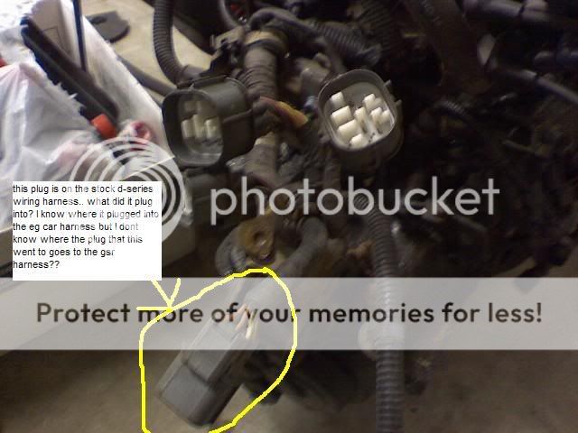
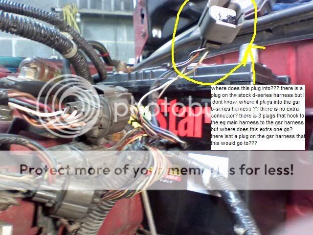
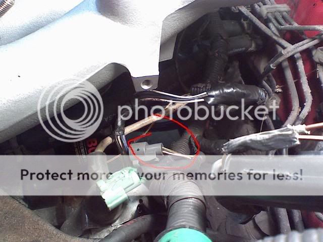
hey guys.. i need some help seeing where these plugs go???
im not using power steering.. let me know thanks a lot
these pics are on the fuse box/ battery side of car
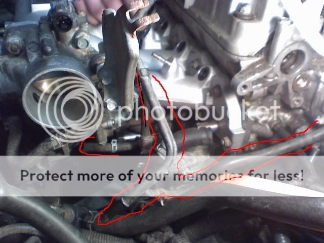
this pic is of harness under intake manifold..
im not using power steering.. let me know thanks a lot
these pics are on the fuse box/ battery side of car
this pic is of harness under intake manifold..
 02-04-2007, 11:51 PM
#2
Honda-Tech Member
Join Date: Oct 2005
Posts: 3,361
Likes: 0
Received 0 Likes
on
0 Posts
the first two plugs plug you dont need to plug in.
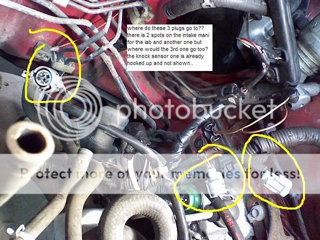
the last three plugs go to
1 purge valve.
2 iacv
3 iat
the first one in the third picture. the one with the longest wire goes to the iacv.
the other two you just have to figure out. swap them if they throw a light
the last three plugs go to
1 purge valve.
2 iacv
3 iat
the first one in the third picture. the one with the longest wire goes to the iacv.
the other two you just have to figure out. swap them if they throw a light
02-05-2007, 12:03 AM
#5
Honda-Tech Member
Join Date: Oct 2005
Posts: 3,361
Likes: 0
Received 0 Likes
on
0 Posts
<TABLE WIDTH="90%" CELLSPACING=0 CELLPADDING=0 ALIGN=CENTER><TR><TD>Quote, originally posted by gotboosthatch »</TD></TR><TR><TD CLASS="quote">the first one in the second picture. the one with the longest wire goes to the iacv..
u mean the 3rd pic???</TD></TR></TABLE>
yes i had to ninja edit that.
u mean the 3rd pic???</TD></TR></TABLE>
yes i had to ninja edit that.
Trending Topics
02-05-2007, 12:18 AM
#8
Honda-Tech Member
Join Date: Oct 2005
Posts: 3,361
Likes: 0
Received 0 Likes
on
0 Posts
<TABLE WIDTH="90%" CELLSPACING=0 CELLPADDING=0 ALIGN=CENTER><TR><TD>Quote, originally posted by fmrprojects »</TD></TR><TR><TD CLASS="quote">you shoulda did all the wiring then drop the motor in the car, woulda made it a lot easier</TD></TR></TABLE>
cheers to you buddy !
!
live and learn
cheers to you buddy
!live and learn
02-06-2007, 02:19 PM
#12
Junior Member
Join Date: Nov 2005
Location: San Antonio, Texas, USA
Posts: 18
Likes: 0
Received 0 Likes
on
0 Posts
if need ne more wire colors just let me know! as wel as pics! this might help
purge yellow/red two wires
vtec green-yellow one wire
vehicle speed sensor black/black/green three wired
ground black/brown multi
map white/yellow/green three wires
tps red/red/yellow three wires
idle air control black/blue two wires
intake air temperature green/red two wires
knock red-blue one wire
oil pressure yellow-red one wire
injector 1 brown/yellow two wires
injector 2 red/yellow two wires
injector 3 green/yellow two wires
injector 4 yellow/yellow two wires
reverse yellow/green two wires
O2 sensor 4 wire plug four wires
Modified by Olivemyhonda at 4:51 PM 2/6/2007
 02-07-2007, 06:04 AM
#16
Honda-Tech Member
Join Date: Mar 2002
Location: MD
Posts: 4,546
Likes: 0
Received 0 Likes
on
0 Posts
okay here it goes... this better help you 
Passenger side 10 pin
Pin Color Function
1 br/blk Drain for o2 sensor
2 wht/red (shielded) o2 sensor
3 br/blk Drain for distributor bundle
4 orange (shielded) Distributor
5 White (blue diamonds) Distributor
6 org/blue (shielded) Distributor
7 wht/blu Distributor
8 blu/grn (shielded) Distributor
9 blu/yel Distributor
10 red/blu (shielded) Knock sensor
All of the above drain wires are grounded to the thermostat housing
Passenger side 14 pin
Pin Color Function
1 wht/grn Alternator
2 org/blk o2 sensor
3 grn/yel VTEC solenoid
4 grn/wht MAP
5 wht/yel (grn diamonds) MAP
6 yel/wht MAP
7 blu/blk VTEC Pressure switch (other pin grounds to thermostat housing)
8 red/blk TPS
9 grn/blu shared signal voltage among sensors (discussed below)
10 yel/blu TPS
11 yel/grn Distributor
12 red/yel IAT
13 red/wht 2 pin coolant temp
14 wht/red Alternator
Driver side 14 pin
Pin Color Function
1 blk/yel Alternator
2 wht/blu Alternator
3 pink/blu Secondaries
4 blk/blu IACV
5 blk/yel VSS (drain for VSS grounds to thermostat housing)
6 orange VSS
7 blue Distributor
8 yel/red oil pressure switch
9 grn radiator fan switch
10 blk (white diamond) Thermostat ground
11 yel/grn Engine coolant temp (cluster temp gauge)
12 yel/blk shared +12v plug (discussed below)
13 grn/blk Reverse light switch
14 yel (grn diamond) Reverse light switch
The shared +5v signal makes its way throughout the harness and connects to the following components (there may be one or two more, I cant remember here at work):
IAT
TPS
ECU coolant temp (2 pin)
The shared +12v yel/blk signal is shared by the following (also might miss one here, hard to remember with all of my notes)
All 4 injectors
Secondary butterflies
IACV
o2 Sensor
The following all ground to the thermostat housing (the brn/blk wires within the harness are the drain wires, while the black wires are signal grounds):
Drain wire for distributor
Drain wire for knock sensor
Drain wire for 02 sensor
Second pin on radiator fan switch (switch on thermo housing)
Second pin for vtec pressure switch
VSS ground (black wire coming off VSS)
Hope this helps! lemme know if I missed anything I typed it up fast
02-08-2007, 08:25 PM
#20
Honda-Tech Member
Join Date: Jun 2003
Location: here, there, everywhere
Posts: 3,021
Likes: 0
Received 0 Likes
on
0 Posts
year and trim level. (ie 92 civic si, 92 civic vx)
and year of the gsr motor you have.
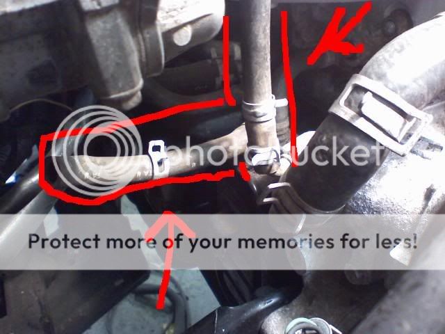
as far as this, it looks like the pcv valve lines.
it plugs into the manifold. looks like you replaced your manifold with a aftermarket one. you need replace the hose so that it reaches the holes on the manifold. (look at the itr and ls set up) and the other hose is for your coolant lines that goes through t/b and iac valve. i'm too lazy to modify your pic. if you want add a 1 and a 2 between the 2 red arrows.
secomdary butterfly solenoid. its on the old stock manifold. not needed on aftermarket single plenium manifolds.
and year of the gsr motor you have.
as far as this, it looks like the pcv valve lines.
it plugs into the manifold. looks like you replaced your manifold with a aftermarket one. you need replace the hose so that it reaches the holes on the manifold. (look at the itr and ls set up) and the other hose is for your coolant lines that goes through t/b and iac valve. i'm too lazy to modify your pic. if you want add a 1 and a 2 between the 2 red arrows.
secomdary butterfly solenoid. its on the old stock manifold. not needed on aftermarket single plenium manifolds.
02-08-2007, 08:27 PM
#21
Honda-Tech Member
Join Date: Jun 2003
Location: here, there, everywhere
Posts: 3,021
Likes: 0
Received 0 Likes
on
0 Posts
guessing on the pic. you have a vx model??
if so, you don't need that extra plug, but you might have to grab the 02 wires and move it from that plug to the other ones.
if so, you don't need that extra plug, but you might have to grab the 02 wires and move it from that plug to the other ones.
02-09-2007, 02:13 PM
#23
Junior Member
Join Date: Nov 2005
Location: San Antonio, Texas, USA
Posts: 18
Likes: 0
Received 0 Likes
on
0 Posts
I THINK YOUR GOING TO HAVE THAT HARNESS LEFT OVER! IS IT ON THE LEFT SIDE OF THE CAR! PASSENGER! IF SO THEN YEAH! ALL HOOK UP BUT ONE!
02-09-2007, 02:36 PM
#24
Honda-Tech Member
Thread Starter
iTrader: (8)
Join Date: Oct 2006
Location: PA, USA
Posts: 3,392
Likes: 0
Received 0 Likes
on
0 Posts
yep left side..thats already been figured out..I need to know where to hookup the double lines that hook to the top of the valve cover and go down???
02-09-2007, 11:55 PM
#25
Honda-Tech Member
Join Date: Jun 2003
Location: here, there, everywhere
Posts: 3,021
Likes: 0
Received 0 Likes
on
0 Posts
if ypur talking about this pic. the big one that you circled goes from the valve cover to the air intake tube
the small one goes to the "wax valve" underneath the throttle body.