
Honda Civic 92-95 EG/EH/EJ OEM Cruise Control Install Guide – Manual Transmission
 11-23-2008, 11:15 PM
#1
Honda Civic 92-95 EG/EH/EJ OEM Cruise Control Install Guide – Manual Transmission
Synopsis
The EG/EH/EJ Honda Civics use a cable-operated cruise control system connected to the pedal assembly under-foot. It was standard equipment on 92-95 Honda Civic 3dr SI/4dr USDM LX & EX, 4dr CDM EX & EX-V/2dr EX(USDM) & SI(CDM). Installing Cruise Control (CC) into your non-CC Civic is a straightforward find-and-replace operation, and can be completed by even inexperienced owners, in my opinion. However, being able to read and understand an automotive wiring diagram and being able to follow directions is imperative. The following guide describes the approximate steps I followed to add CC to a "vanilla" manual-transmission Canadian Domestic Market (CDM) 3dr 1994 Honda Civic CX; the only fancy option this car came with originally was OEM floor mats and mud flaps. It was totally bone stock, and I had only ever put oil, gas and washer fluid into my car in the six years I had owned it up to the point where I added this option. Since then, I have added a number of OEM options, including a Rear Wiper, Headlight Washers, EDM Rear Fog Lamp, Power Locks, Power Windows, Power Folding Heated Mirrors and a Trunk Light, the instructions for some of which I have written up in other DIYs on this site.
Herein, I give detailed instructions on what to remove, and *some* details on how to remove it and re-install it, but I EXPECT you to have a USDM/CDM Helms Service Manual to consult for the major details on how to take stuff on your car apart, and for how to access some of the areas I describe below (eg., driver's footwell). No sense in me trying to tell you how to do this, when they have already done an excellent job of it already.
Preparation
Notes on wiring
Wiring will likely take you the MOST amount of time out of all the operations involved in this project. My recommendation is, and if you're like me and want as clean an install as possible, pull the whole dash, gauge cluster and cabin under-dash/footwell wiring harnesses apart and pull whole, uncut wires, starting at the CC brain and going all the way to the respective switches or connections. At the very least, get as much wiring as possible, you will thank me later. If you want to cheat a little, you could cut the wires and pull them through the loom, though it's sometimes difficult to figure out where they go.
Pulling ALL the wires, uncut -- while painful -- makes the re-wiring exercise considerably more pleasant, and guarantees you have exactly the right length, gives you the exact OEM wire colours, means you don't have to go out and buy your OWN wire, and will save time stripping and crimping wires back together again (and eliminates the risk of a bad connection due to a poor crimp job). I didn't always follow BLK (ground) wires to their terminal, so buy yourself a 25ft roll of 16 gauge BLK wire, and you'll be set.
Wiring Connectors
To patch together cut wires, I recommend using Bullet connectors. These attach & detach readily and are self-shielding. I suppose a cautious person would electrical-tape all the connections, but I didn't. You will need a few T-Taps or Wire Tap connectors, too. I purchased my electronics parts over the phone from A-1 Electronics - see http://www.a1parts.com/ (WARNING: TERRIBLE WEBSITE. GODAWFUL.); these had the best prices around Canada that I could find, and domestic shipping was a flat $10. I ordered a pack of 100 for each of Male & Female 14-16 (blue) & 16-18 (red) gauge Bullet connectors, and a pack of 100 of each of 14-16 (blue) & 16-18 gauge wire-taps (T-Taps).
Americans can just look on eBay; there's dozens of dealers selling large bulk packs of bullet connectors and wire taps.
Pin Removal
You'll have to do a bit of this. A tiny screwdriver is your friend. Look up on honda-tech.com the correct way to remove pins from connectors.
Note on Order of Operations
The instructions, as printed below, aren't necessarily meant to be followed linearly as a step-by-step process of removal and then re-installation. Read the whole thing through, first, to get an idea of what you're up against. You will have to jump around a bit from section to section as you see fit. There is no real "wrong" order to do the install, but you will run in to obvious roadblocks, such as the need to remove the foot pedals from your own vehicle, for example, early on in order to work freely in the cramped driver's footwell... but to do this, I think you also have to remove the steering column, so you'll first have to learn how to remove the steering column properly from your Helms manual.
Time Required
This project is no cakewalk. It took me about about a day and a half (8am to 5pm) to remove all the parts from a salvage yard wreck. Reinstallation took longer: about two whole long days (7am to 8pm). I was a total novice, though.
Disclaimer
Every effort has been made to make these instructions as complete and accurate as possible, but no warranty or fitness is implied. The information is provided on an “as is” basis. The author(s) and the website/publisher(s) shall have neither liability nor responsibility to any person or entity with respect to any loss or damages or inconvenience arising from the information contained herein. Read: Don't muck up your vehicle and try to blame me or anyone else without doing your own due diligence and research.
Parts Required & Removal Instructions
Under Hood
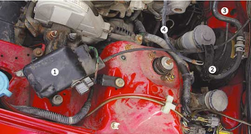 Figure 1. Engine compartment, mid-way through install. (1) is cruise actuator. (2) is new
throttle & actuator cable guide (not bolted down yet). (3) is grommet plug in firewall (to be removed). (4) is
throttle cable (attached to gas pedal).
 Figure 2. Engine compartment/firewall. (1) is cruise actuator cable & plug. (2) is firewall
grommet (to be removed) and the metal end-cap on the end of actuator cable. (3) is
throttle cable. (4) is brake booster and master brake cylinder.
Cabin: Dashboard

Figure 3. Non-cruise (left) vs. cruise pedals. (1a) is 2-pin brake light switch. (1b) is 4-pin
cruise switch with added connection to disengage cruise when brake is depressed. (2) is
where throttle is attached. (3) is where cruise actuator cable is attached.

Figure 4. M/T clutch switches. (1) is M/T clutch CC disengagement switch.
(2) is regular "clutch is depressed" switch (don't touch).

Figure 5. Left side of body in driver's footwell. (1) is top bolt which is very hard to get out.
Note large wiring loom above. (2) is brown junction connector between main harness and
engine compartment harness. Cruise actuator wires connect through here. (3) is ground
bolt, which will be obscured by the cruise brain and bracket. Note 10cm length of BLK wire
I extended from this bolt to ease grounding of wiring after installation of bracket.
Installation Instructions
Under Hood
Cabin: Steering Column
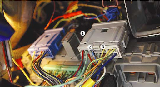
Figure 6. Top of under-dash fuse box. (1) is grey junction connector.
(2) is BLU (Ignition coil) wire. (3) is YEL/BLU (Speed Sensor) wire.
Test Drive
Good Luck and enjoy 'cruising' around with your upgrade.
DeSchlong
November, 2008
Synopsis
The EG/EH/EJ Honda Civics use a cable-operated cruise control system connected to the pedal assembly under-foot. It was standard equipment on 92-95 Honda Civic 3dr SI/4dr USDM LX & EX, 4dr CDM EX & EX-V/2dr EX(USDM) & SI(CDM). Installing Cruise Control (CC) into your non-CC Civic is a straightforward find-and-replace operation, and can be completed by even inexperienced owners, in my opinion. However, being able to read and understand an automotive wiring diagram and being able to follow directions is imperative. The following guide describes the approximate steps I followed to add CC to a "vanilla" manual-transmission Canadian Domestic Market (CDM) 3dr 1994 Honda Civic CX; the only fancy option this car came with originally was OEM floor mats and mud flaps. It was totally bone stock, and I had only ever put oil, gas and washer fluid into my car in the six years I had owned it up to the point where I added this option. Since then, I have added a number of OEM options, including a Rear Wiper, Headlight Washers, EDM Rear Fog Lamp, Power Locks, Power Windows, Power Folding Heated Mirrors and a Trunk Light, the instructions for some of which I have written up in other DIYs on this site.
Herein, I give detailed instructions on what to remove, and *some* details on how to remove it and re-install it, but I EXPECT you to have a USDM/CDM Helms Service Manual to consult for the major details on how to take stuff on your car apart, and for how to access some of the areas I describe below (eg., driver's footwell). No sense in me trying to tell you how to do this, when they have already done an excellent job of it already.
Preparation
Notes on wiring
Wiring will likely take you the MOST amount of time out of all the operations involved in this project. My recommendation is, and if you're like me and want as clean an install as possible, pull the whole dash, gauge cluster and cabin under-dash/footwell wiring harnesses apart and pull whole, uncut wires, starting at the CC brain and going all the way to the respective switches or connections. At the very least, get as much wiring as possible, you will thank me later. If you want to cheat a little, you could cut the wires and pull them through the loom, though it's sometimes difficult to figure out where they go.
Pulling ALL the wires, uncut -- while painful -- makes the re-wiring exercise considerably more pleasant, and guarantees you have exactly the right length, gives you the exact OEM wire colours, means you don't have to go out and buy your OWN wire, and will save time stripping and crimping wires back together again (and eliminates the risk of a bad connection due to a poor crimp job). I didn't always follow BLK (ground) wires to their terminal, so buy yourself a 25ft roll of 16 gauge BLK wire, and you'll be set.
Wiring Connectors
To patch together cut wires, I recommend using Bullet connectors. These attach & detach readily and are self-shielding. I suppose a cautious person would electrical-tape all the connections, but I didn't. You will need a few T-Taps or Wire Tap connectors, too. I purchased my electronics parts over the phone from A-1 Electronics - see http://www.a1parts.com/ (WARNING: TERRIBLE WEBSITE. GODAWFUL.); these had the best prices around Canada that I could find, and domestic shipping was a flat $10. I ordered a pack of 100 for each of Male & Female 14-16 (blue) & 16-18 (red) gauge Bullet connectors, and a pack of 100 of each of 14-16 (blue) & 16-18 gauge wire-taps (T-Taps).
Americans can just look on eBay; there's dozens of dealers selling large bulk packs of bullet connectors and wire taps.
Pin Removal
You'll have to do a bit of this. A tiny screwdriver is your friend. Look up on honda-tech.com the correct way to remove pins from connectors.
Note on Order of Operations
The instructions, as printed below, aren't necessarily meant to be followed linearly as a step-by-step process of removal and then re-installation. Read the whole thing through, first, to get an idea of what you're up against. You will have to jump around a bit from section to section as you see fit. There is no real "wrong" order to do the install, but you will run in to obvious roadblocks, such as the need to remove the foot pedals from your own vehicle, for example, early on in order to work freely in the cramped driver's footwell... but to do this, I think you also have to remove the steering column, so you'll first have to learn how to remove the steering column properly from your Helms manual.
Time Required
This project is no cakewalk. It took me about about a day and a half (8am to 5pm) to remove all the parts from a salvage yard wreck. Reinstallation took longer: about two whole long days (7am to 8pm). I was a total novice, though.
Disclaimer
Every effort has been made to make these instructions as complete and accurate as possible, but no warranty or fitness is implied. The information is provided on an “as is” basis. The author(s) and the website/publisher(s) shall have neither liability nor responsibility to any person or entity with respect to any loss or damages or inconvenience arising from the information contained herein. Read: Don't muck up your vehicle and try to blame me or anyone else without doing your own due diligence and research.
Parts Required & Removal Instructions
Under Hood
- Cruise actuator: black box on RH side of engine compartment. See Figure 1.
- Un-bolt from body. Get as much wiring as possible.
- Cable guide: metal piece which retains throttle and cruise actuator cables. See Figure 1.
- Unbolt and pry out the throttle cable (not the actuator one, leave it attached).
- Firewall plug: plastic/rubber connection/plug through which the actuator cable enters the cabin and attaches to the pedal assembly. See Figure 1 & 2.
- Un-hook the cable from the pedal assembly in the footwell. Grasp the metal dongle at the end of the cable and wiggle it out. Twist and pull the actuator plug from the hole in the firewall. Pull the cable and connection/plug into the engine compartment. If you did this step last, then the whole actuator assembly should now be free.
throttle & actuator cable guide (not bolted down yet). (3) is grommet plug in firewall (to be removed). (4) is
throttle cable (attached to gas pedal).
grommet (to be removed) and the metal end-cap on the end of actuator cable. (3) is
throttle cable. (4) is brake booster and master brake cylinder.
Cabin: Dashboard
- Gauge cluster with cruise light: you'll need the cluster as it has the green cruise light in the bottom right corner.
- Follow Helms manual instructions for removal.
- CC gauge cluster light connector & pigtail: connector lights up the cruise light in the gauge cluster, tells you when your CC is enabled.
- This is the green connector on the bottom-centre-left of the gauge cluster, when looking at the back (yellow is SRS). Get it, and as much wiring as possible, or trace back to under-dash fuse box and/or CC brain.
- Dashboard main switch & pigtail: switch on left side of dash that engages the CC computer brain.
- Carefully pry it out of the dash. Trace back its wiring and get as much as possible. I think it connects to a large splitter behind the dash in that area.
- (Optional) "Neo-wedge bulbs": bulbs that light up dashboard switches. There is a chance that the main CC dash switch has blown bulbs (mine did), so to resolve this problem, grab some extra bulbs.
- Pry out the eg., rear defrost switch and/or hazard light switch and twist out the bulbs with a flathead screwdriver. They are all the same and will fit the CC switch.
- Put these somewhere safe/padded from impacts and the wrath of your tools.
- For vehicles WITH CC & SRS
- Clock spring: Under steering wheel, it is the circular thing bolted to assembly which holds the light & washer switches, maintains contact with the SRS features, and the horn & CC switches while allowing steering wheel to spin.
- Follow Helms manual instructions for removal. My car doesn't have SRS, but I take it they can blow up in your face, so take necessary precautions. Be careful if the airbag is still intact! Helms is explicit in this regard. You'll need a Torx screwdriver and a 19mm socket to take off the steering wheel. I've had the Torx screw strip on me before ... so, consider yourself warned! Use lots of pressure before you start turning the screw.
- Set/resume switch assembly & cover.
- These are mounted on the steering wheel. Removal of the switches is pretty obvious once you look inside. Don't forget the cover!
- Clock spring: Under steering wheel, it is the circular thing bolted to assembly which holds the light & washer switches, maintains contact with the SRS features, and the horn & CC switches while allowing steering wheel to spin.
- For vehicles WITH CC, WITHOUT SRS: these vehicles are REALLY hard to find. AFAIK, only CDM 1992 Honda Civic 3dr SI/4dr EX & EX-V and maybe CDM 1993 2dr Civic EX/SI came with this setup (but doubtful).
- Steering wheel with cruise buttons.
- Wheel will look like an SRS-enabled wheel (four prongs), but without a bag in the centre, just a hard Honda-branded centre piece in the shape of an airbag. Buttons on either side for horn. Consult Helms for proper removal. You'll need a 19mm socket.
- Slip ring: bolted to assembly over turn-canceler which holds the light & washer switches, maintains contact with horn & cruise switches while allowing steering wheel to spin.
- Unscrew and remove. Get as much wiring as possible, or trace back wiring all the way to CC brain. Note that the horn wire doubles back to connect with headlight/horn combination switch.
- Steering wheel with cruise buttons.
- Pedal assembly: bolted to the firewall are the gas & brake assembly unit, which is different on a car with CC. It has a special bracket into which clips the CC actuator cable. See Figure 3.
- You need the whole thing and it's a real pain to get out. You need a deep 12mm socket, if memory serves. Helms should help for instructions on proper removal. I recall fighting against the brake cylinder trying to wiggle it out of there. The pedals are connected to brake/throttle with cotter pins - be sure to keep these (or you can re-use your existing ones).
- I think you have to take the whole steering column out to get it off. This might be a good time to consider whether you also want a tilt steering column if you don't have one already. NOTE: SRS columns WILL NOT fit non-SRS ignition cylinders! The neck does not narrow where the key cylinder mounts.
- Brake light switch (4-pin connector) & pigtail: Screwed in to the pedal assembly on a CC vehicle is a 4-pin brake light switch. See Figure 3. This means 2 additional pins to a non-CC vehicle. The additional connections disengage the CC when the brake is depressed.
- Leave the switch screwed in to the pedal assembly, but be sure to get the pigtail and as much wiring as possible, or trace back to computer brain / under-dash fuse box.
Figure 3. Non-cruise (left) vs. cruise pedals. (1a) is 2-pin brake light switch. (1b) is 4-pin
cruise switch with added connection to disengage cruise when brake is depressed. (2) is
where throttle is attached. (3) is where cruise actuator cable is attached.
- M/T clutch pedal switch: switch which disengages CC when the clutch is depressed. See Figure 4.
- Unscrew and retain. Get as much wiring as possible, or trace it back to CC brain. BLK might be (oddly enough) grounded through a connection at the under-dash fuse box.
- M/T Cruise computer brain & bracket: this is where the magic happens. Based on my study of the wiring diagram, an A/T brain CAN BE USED on an M/T vehicle. The PNK wire is just attached to something different than on a M/T vehicle.
- 10mm bolts attach it to the body. Leave the brain attached to the bracket. The bottom screw is easy to remove, but the top one is a real pain. It is semi-obscured by a massive bundle of wiring which fights you the whole way. Be persistent. Prepare to spend a lot of time trying to remove the bolt. See Figure 5.
- If you don't care about wiring colours, just cut the pigtail and be done with it.
- If you're like me, and want as clean an install as possible, I pulled the whole dash wiring harness apart (just in that area!) and pulled whole, uncut wires, going all the way to their respective switches or connections.
- The three exceptions I made to this were BLK/YEL, BLU, & YEL/BLU (and BLK, but I always just cut BLK grounds), each of which are split deep within the main wiring harness (I know this because I have pulled a main wiring harness and traced the connections back).
- GRN/WHT might also be added to this list, though I have seen two configurations: one where the connection is deep in the main wiring harness, another where the connection meets at the 4-pin brake pedal switch.
- These wires can be tapped in other more accessible locations on reinstall. Always get as much wiring as possible, you will thank me later. Pulling all the wires, while painful, made the re-wiring exercise considerably more pleasant.
- (Optional) Actuator wiring through engine wiring connector junction: the actuator wiring passes through a junction before entering the engine compartment. See Figure 5. If you want your wiring to be as close to OEM as possible, also get this junction so that your wires will pass through it too.
- It's brown, and located in the top back left corner of the footwell. There is a white plastic bracket that holds two of them in place there. To remove the junction connector, I believe you have to push the whole thing quite hard towards the firewall, to get it off its mounting clip. Cut all the wires that aren't for the actuator (ie., leave intact BRN, BRN/WHT, BRN/BLK). You can probably pull the actuator wires from the engine compartment through into the footwell to remove the whole wires, if you have removed the actuator assembly and clipped those wires in the engine compartment already. Is that clear? Probably not.
Figure 4. M/T clutch switches. (1) is M/T clutch CC disengagement switch.
(2) is regular "clutch is depressed" switch (don't touch).
Figure 5. Left side of body in driver's footwell. (1) is top bolt which is very hard to get out.
Note large wiring loom above. (2) is brown junction connector between main harness and
engine compartment harness. Cruise actuator wires connect through here. (3) is ground
bolt, which will be obscured by the cruise brain and bracket. Note 10cm length of BLK wire
I extended from this bolt to ease grounding of wiring after installation of bracket.
- Cruise actuator.
- Bolts right on. See Figure 1. You kept the bolts, didn't you?
- Cable guide
- Remove and replace your current cable guide with the new one. See Figure 1. Add a bit of lithium grease or oil to ease the throttle cable into its new home in the new guide.
- Firewall plug
- Pop your existing blank delete plug out with a flathead screwdriver. See Figure 1. Cover it with a cloth if you don't want to scratch the paint. In the footwell, there is some rubber padding flush against the firewall. It will have a pre-cut circular area which you can pull out to expose the hole in the firewall through which the actuator cable enters the cabin. I am pretty sure I had removed the existing gas/brake pedals already (see below) to access this area. Install the actuator plug and feed the actuator cable through.
- Wiring notes
- After poking the BRN, BRN/BLK & BRN/WHT through the large rubber grommet (see below), I cable tied them parallel to the exising wiring in a 3/8" split plastic wiring loom through the engine compartment. The BLK wire from the actuator I extended to the ground bolt by the washer bottle.
- Gauge cluster with cruise light
- Swap in your new gauge cluster after you've completed the wiring for the cruise light.
- To keep your same odometer mileage after a gauge swap, you need to open up the cluster and swap the speedometer assembly. It's quite simple and there is a DIY on honda-tech.com with instructions on how to do this.
- Bonus: You get a free tachometer, if you didn't have one before. w00t.
- RED/BLU goes to the CC brain. YEL can be tapped in to by the fuse box. RED/BLK can be tapped in to using the wiring splitter in your dash harness approximately behind where the main switch goes. BLK goes to ground.
- Dashboard main switch & pigtail
- Pry out the blank, install your new main switch.
- Plug in your newly wired connector: LT GRN comes from the brake switch, first passing through the junction connector on top of the fuse box. BLK/YEL and RED/BLK can be tapped in to using the wiring splitter in your dash harness approximately behind where the main switch goes. RED too, I believe, if not then tap in to a RED wire in the area. BLK goes to ground.
Cabin: Steering Column
- CAUTION: DON'T BREAK THE TABS WHEN REMOVING THE STEERING COLUMN COVERS! You've been warned. It's very easy to do if you just reef on it. Pry each apart carefully. Be patient. You probably broke the tabs on the column cover on the car you salvaged parts from, and made a mental note not to do that on your own vehicle.
- For vehicles WITH CC & SRS: though I did not work on a vehicle with SRS, I have seen enough of them, and below is my best guess as to how to install CC on a vehicle so-equipped.
- Clock spring
- NOTE: NON-SRS ONLY: Remove your steering wheel and the column covers. Replace yours with the new one wired with CC. Connect up LT GRN/BLK, LT GRN/RED, BLU/RED and whatever other wires are down there. LT GRN/BLK & LT GRN/RED both run all the way back to the CC brain.
- SRS vehicles, see post #19 below to see where LT GRN/BLK and LT GRN/RED terminate before they enter the SRS harness and travel up to the SRS clock spring.
- Set/resume switch assembly & cover
- Your non-CC steering wheel should have a blank cover over where the set/resume switch goes. Replace it with the new set/resume switch, and affix the new cover. Plug it all in and put it all back together
- Clock spring
- For vehicles WITH CC, WITHOUT SRS
- Slip ring
- Remove your steering wheel and the column covers. Slip ring screws on over the turn-canceler. Note that the buttons receive their constant power from the same wire that powers the horn, BLU/RED. This was confusing for me, as I didn't find it clear on the Helms wiring diagram. LT GRN/BLK & LT GRN/RED both run all the way back to the CC brain. BLU/RED (the horn) doubles back to attach to the headlight switch connector.
- Steering wheel with cruise buttons
- Plug connector into the slip ring, line up the little prongs on the slip ring, and on the turn canceler, bolt it down. CAUTION: Watch that you line up the turn canceler properly. There are two little metal tabs that stick up and meet with the two grooves on the back of the steering wheel, near the hole for the steering column. If you don't line them up, and tighten the steering wheel down, you WILL bend the metal pieces and this might affect performance (ie., turn canceling).
- Slip ring
- Actuator wiring through engine (and wiring connector junction)
- The bundle of wire that enters the engine compartment passes through a large rubber grommet. The simplest way to pass your new wires through is just to poke a hole through the rubber. Disassembling the bundle and adding the new wires to it is a daunting task which I did not undertake, though it *would* look more OEM.
- If you followed my instructions above and took the *optional* step of getting the entire junction connector, the following is a painful step, but I found it worthwhile, somehow.
- You need to detach the brown connector, open it up, and insert the BRN, BRN/BLK, BRN/WHT pins into the correct location. See Figure 5. Don't muck it up like I did, and have to try to extract pins while cramped up in that tight location. You really only get one shot at it.
- Close up the connector, plug it back together, and re-mount it.
- If you didn't take the junction connector above, then just bypass the junction connection and connect up BRN, BRN/BLK and BRN/WHT to the wires that go into the engine compartment.
- This would also be the time to add any other wiring you would like to send to the engine compartment. I added a WHD/RED wire for a future addition of OEM headlight washers.
- Also, this is a good time to drop down the 1-pin fog light option connector which is blue-taped high above the white brace holding the two junction connectors, possibly even behind the padded rubber matting. If you have a 94-95 Civic, it's there, believe me. Keep hunting. (92-93 are outta luck, sorry.)
- Brake light switch (4-pin connector)
- Make a note of where the WHT/GRN & GRN/WHT wires are on the 4-pin connector (I wrote with a Sharpie right on the plastic), then extract them.
- In the footwell, extract the female pins from the your non-CC brake connector (WHT/GRN, GRN/WHT). You might choose to splice the GRN/WHT wire which goes to the CC brain here.
- Swap in the 4-pin connector, and connect your existing WHT/GRN, GRN/WHT wiring to the the same place they were.
- Route one LT GRN and the GRY (and a GRN/WHT if necessary) to the CC brain, the other LT GRN passes through the grey junction on the under-dase fuse box (Figure 6) before travelling on to the Main Switch.
- M/T clutch pedal switch
- USDM CX/VX and CDM VX models have an "upshift switch" here. If you want cruise, you're gonna have to ditch this feature, or figure out a way to re-wire it (see below). Other models just have a dud bolt.
- If you have the dud bolt, unscrew it and it with the M/T cruise clutch switch. See Figure 4.
- If you have the VX, you can leave your current switch there and figure out a way to mount the CC clutch switch by fashioning a custom made bracket.
- PNK runs to the CC brain, BLK goes to ground.
- M/T Cruise computer brain & bracket
- CDM vehicles will have to remove the DRL relay here. Once again, you will have to fight with the large wiring loom as you remove the 10mm bolt. See Figure 5.
- Before you attach the bracket, you might consider hooking up a short lead of BLK wire (~10cm) to the ground here that you're about to cover up. See Figure 5. I used a U-terminal, and slid it under the grounding bolt. On the other end, I used an O-terminal. Through it, I put a small screw with a nut. As I completed the wiring, I led the BLK ground wires terminated with their own O-terminal, back to this screw/nut, which allowed for way easier grounding than making everything reach behind the CC brain for a direct ground. Not OEM, but pretty clean, nonetheless.
- Bolt the bracket in on top and bottom.
- CDM vehicles will bolt the DRL relay to one of the bolt holes on the top of the bracket, on the left or right of the CC brain.
- Plug in the 14-pin connector. It's a tight fit back there.
- Wiring notes:
- BLK/YEL (power) can be obtained by tapping in to PIN 9 on C441 (back side of fuse box).
- BLU (Ignition Coil) & YEL/BLU (Speed Sensor) can be tapped into behind the grey connector junction on top of the under-dash fuse box. See Figure 6.
- Pedal assembly
- The pedal assembly is one of the last things you'll put back on. You'll have it off basically right at the start so that you can work a little easier in the cramped space of the driver's footwell.
- Take original off. As mentioned above, I think you have to take the whole steering column out to get it off. Some 12mm bolts and attachments to the brake cylinder (cotter pin) and the throttle cable all hold it in.
- Wiggle the new one in, and you might need someone on the outside to move the master brake cylinder around so you can get it in the right place. Hook up the brake and the throttle & cruise actuator cables.
- Attach the 4-pin brake light switch.
- Install your new tilt steering column, if you grabbed one of those.. ooh yeah.
Figure 6. Top of under-dash fuse box. (1) is grey junction connector.
(2) is BLU (Ignition coil) wire. (3) is YEL/BLU (Speed Sensor) wire.
Test Drive
- I wouldn't completely reassemble all your parts before your first test drive. Leave off certain pieces of trim to make it easier to troubleshoot if you encounter problems.
- Head out somewhere with no traffic, and test out your system.
- With the car running, normal operation will involve:
- Pressing the main dash CC button in; the button indicator light will glow green,
- Pressing SET on the steering wheel buttons at a speed >50km/h, and
- The CC gauge cluster light will illuminate.
- With the car running, normal operation will involve:
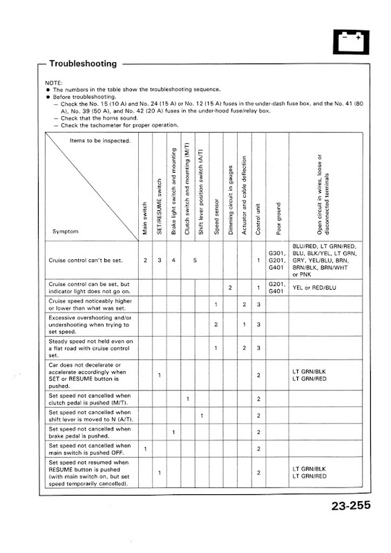
- If it does not work on the first try, follow the troubleshooting directions in your Helms TO THE LETTER! Pg 23-255. It will help you track down the problem the quickly. Trust it.
- That said, I will add that testing your ground connections (all of 'em) is a good test to begin with.
- A blown bulb (eg., in the cluster) will not affect the operation of your CC, but should be replaced!
Good Luck and enjoy 'cruising' around with your upgrade.
DeSchlong
November, 2008
Last edited by deschlong; 12-10-2014 at 04:58 PM. Reason: Apr/13:Fixed broken pic links; Dec/14:Fixed typo, added info for n00bs
 11-24-2008, 06:51 AM
#2

Nice writeup, especially the photos. What you did is very similar to what I did. I am going to link your post from my site. :-) See http://honda.lioness.googlepages.com/cruisecontrol
An excellent resource for depinning Honda electrical connectors appears at http://www.in.honda.com/Rjanisis/pubs/SB/B00-039.PDF .
An excellent resource for depinning Honda electrical connectors appears at http://www.in.honda.com/Rjanisis/pubs/SB/B00-039.PDF .
 11-24-2008, 08:57 AM
#5
Yes. My 93 DX had SRS but not cruise control, and I had to replace the clock spring when adding CC. I found the DX's SRS clock spring does not have the pin leads and connectors for the steering wheel set/resume switch. Depinning yada does not work in this instance, because of the ribbon cable design that the clock springs use.
11-24-2008, 07:36 PM
#6

What is the first thing I should check because my cruise control on my 92 EH3 is not working. The button light comes on when I press the CC button on the dash but holding or pressing SET never works nor turns on the light in the gauge cluster. My CC used to work a few months ago but I don't remember what exactly I have done since then to make it stop working. But I recall once seeing the CC light on in the gauge cluster!!
11-25-2008, 06:50 AM
#7
What is the first thing I should check because my cruise control on my 92 EH3 is not working. The button light comes on when I press the CC button on the dash but holding or pressing SET never works nor turns on the light in the gauge cluster. My CC used to work a few months ago but I don't remember what exactly I have done since then to make it stop working. But I recall once seeing the CC light on in the gauge cluster!!
The most important page of the troubleshooting guide for wires appears as the last photo at http://honda.lioness.googlepages.com/cruisecontrol .
My new used CC did not work right after installation. Using the wiring troubleshooting, I very quickly narrowed the problem to the brake switch and the set/resume switch. I simply had not adjusted the brake switch properly. I had monkeyed with the internals of the set/resume switch and had lost a tiny ball bearing that was critical to its operation. I picked one up at the junkyard and put it in. All tests passed. The CC worked.
Trending Topics
03-31-2009, 08:01 AM
#9
Honda-Tech Member
I have a NRG quick release shorty hub with a momo wheel. The car has no clock spring anymore. Do you know if it's possible to mount the clock spring with this setup? The car was setup this way when I bought it. I would like to add cruise, but I don't want to mount the set and accel switches somewhere on the dash, I want them on the wheel. Not sure if this is possible however?
04-02-2009, 08:28 PM
#10
Honda-Tech Member
Heres a question as well. Is it possible to not use the main switch with the cruise control? By that I mean can't you just take the blk/yel and lt grn wires to positive so that the system will be on all the time? I don't want to have to turn it on, I'd rather just have it on when I start the car. Do you know?
04-02-2009, 08:55 PM
#11
@rickkane:
Dang I thought I answered your earlier question. A clock spring with that setup likely will not work. What you need instead is a slip ring from a CDM Civic Si or EX that came with no SRS. You won't find one in your country's junkyards because they didn't exist there... however, it's possible you can order one new from a dealer or online. P/N 35257-SR3-C01
After you tackle that hurdle, then you have to figure out how you're going to mount your switches on the steering wheel. This will obviously be a custom job.
As for keeping the main switch ON all the time... initially I guess it seems like it would be fine. However, Honda's engineers are infinitely smarter than both of us ... I would imagine they had a reason why they would have a dashboard mounted main switch, otherwise they woulda saved the production cost of all those switches. I would advise against -- I just don't know why .... yet.
I wish I knew where I could tell you to steal a 5-pin connector that matches the one which connects the CDM slip ring. I know I saw one just like it in a stock car. I do know that the Rear Fog Lamp switch and the Headlight Washer switch use the same connector but that doesn't really help you.
EDIT: 5-pin connectors can be found in the tail-lamp area of 5G Sedans, and probably Coupes.
Last edited by deschlong; 10-03-2010 at 09:04 AM. Reason: Found the 5-pin connectors.
04-02-2009, 09:22 PM
#12
Honda-Tech Member
I agree that Honda's engineers are quite alot smarter than I. My main reason for wanting the system on all the time is because I have the coin pocket installed in place of the dimmer/sunroof switch and where the main cc switch would go. So it's kind of me being lazy as well. Thanks for the help though! I suppose I can ditch the coin pocket, and put the on switch in there. I'll check ebay for the slip ring. Cheers.
04-02-2009, 09:44 PM
#13
You won't find the slip ring on eBay. That thing is so rare and obscure, it never shows up. I've had an automatic search set up for one for about a year and I have never had a hit.
If you got yourself an EDM Rear Defogger switch that mounts on the opposite side of your USDM Rear Defog switch, you could slide your CC main switch in there... that is, if you don't have a Front Fog Lamp switch in there already....
If you got yourself an EDM Rear Defogger switch that mounts on the opposite side of your USDM Rear Defog switch, you could slide your CC main switch in there... that is, if you don't have a Front Fog Lamp switch in there already....
04-05-2009, 02:12 AM
#14

What is the first thing I should check because my cruise control on my 92 EH3 is not working. The button light comes on when I press the CC button on the dash but holding or pressing SET never works nor turns on the light in the gauge cluster. My CC used to work a few months ago but I don't remember what exactly I have done since then to make it stop working. But I recall once seeing the CC light on in the gauge cluster!!
03-16-2010, 02:02 PM
#15
Honda-Tech Member
So here's how I ended up mounting the cruise controls, since I have the NRG quick release. I'd rather have it on the wheel, but this is working out fine, as I don't have the power mirrors. You recognize that set/resume switch don't you? I just cut the power mirror delete panel to fit the switch, and away it goes. Works brilliantly, and the best part is the wires are still the same colors. Check out the black panel as well, that's why I needed the black climate control! 
@rickkane:
Dang I thought I answered your earlier question. A clock spring with that setup likely will not work. What you need instead is a slip ring from a CDM Civic Si or EX that came with no SRS. You won't find one in your country's junkyards because they didn't exist there... however, it's possible you can order one new from a dealer or online. P/N 35257-SR3-C01
After you tackle that hurdle, then you have to figure out how you're going to mount your switches on the steering wheel. This will obviously be a custom job.
As for keeping the main switch ON all the time... initially I guess it seems like it would be fine. However, Honda's engineers are infinitely smarter than both of us ... I would imagine they had a reason why they would have a dashboard mounted main switch, otherwise they woulda saved the production cost of all those switches. I would advise against -- I just don't know why .... yet.
I wish I knew where I could tell you to steal a 5-pin connector that matches the one which connects the CDM slip ring. I know I saw one just like it in a stock car. I do know that the Rear Fog Lamp switch and the Headlight Washer switch use the same connector but that doesn't really help you.
 08-16-2010, 07:00 AM
#17
Honda-Tech Member

Join Date: Jul 2010
Location: Cocoa Beach
Posts: 5
Likes: 0
Received 0 Likes
on
0 Posts
I pinned the lt grn/blk and lt grn/red wires to the CC connector. Then, I unpinned the lt grn/blk and lt grn/red wires from the SRS connector on my donor car. The donor connector had 4 pins. The only SRS connector I found that looked like the donor vehicle connector has a place for 8 pins. Is this the right one to use?
08-16-2010, 07:17 AM
#18
^^ Remember - as I wrote in the DIY, I don't have SRS (my car is CDM), so it is difficult for me to know what you are referring to without photos or diagrams if it is related even tangentially to SRS equipment.
Here's another DIY for a USDM vehicle ... possibly the answer is in there?
Here's another DIY for a USDM vehicle ... possibly the answer is in there?
08-19-2010, 07:58 AM
#19
Honda-Tech Member
Join Date: Mar 2008
Location: Rochester, NY, USA
Posts: 5
Likes: 0
Received 0 Likes
on
0 Posts
I pinned the lt grn/blk and lt grn/red wires to the CC connector. Then, I unpinned the lt grn/blk and lt grn/red wires from the SRS connector on my donor car. The donor connector had 4 pins. The only SRS connector I found that looked like the donor vehicle connector has a place for 8 pins. Is this the right one to use?

If you look at figure 6 in DeSchlong's writeup, this connector is located in the upper right corner, just out of camera range. It connects to the existing SRS harness. The two homebrew wires I added are labeled. The four wires in my SRS harness that fed into this connector were all gray, so I couldn't match up wire colors. You'll find two empty terminals in this connector for your donated cruise wires. Make sure the light green/black wire is the one connected to the outside terminal and you should be all set.
10-03-2010, 07:20 AM
#20
Honda-Tech Member
Join Date: Jul 2010
Location: Cocoa Beach
Posts: 5
Likes: 0
Received 0 Likes
on
0 Posts
I have installed all the used CC components in my '95 VX. The CC does not work and I found the brake light switch in the pedal with a short. I fixed the brake light switch short. I have gone through all the steps in the shop manual and replaced the CC control module and the actuator. I still cannot get it to work. Is there any other troubleshooting I can do? The only thing that did not jive was the rotation of the front tire off the ground and getting 0-5 volts alternating on the yelow/blue wire from the speed sensor. I only get 0-4.7volts. Could this cause the CC to not work? Is the VSS bad?
10-03-2010, 07:31 AM
#21

I have installed all the used CC components in my '95 VX. The CC does not work and I found the brake light switch in the pedal with a short. I fixed the brake light switch short. I have gone through all the steps in the shop manual and replaced the CC control module and the actuator. I still cannot get it to work. Is there any other troubleshooting I can do? The only thing that did not jive was the rotation of the front tire off the ground and getting 0-5 volts alternating on the yelow/blue wire from the speed sensor. I only get 0-4.7volts. Could this cause the CC to not work? Is the VSS bad?
Are the rubber stoppers that press on the brake and clutch switches damaged or missing? You should give more details about your problem. Does the light in the cc button or in the cluster turn on when you try to activate cc?
10-03-2010, 08:27 AM
#22
^ Agree with RonJ - we need more details about the problem. It looks like the issue dates back to your earlier post back in August - so we also need more timely responses in order to help. Meanwhile, here is the troubleshooting diagram. Have you checked all your grounds? Have you double and triple checked all your wiring? A systematic approach is the only way to solve this.
10-06-2010, 05:41 AM
#23
Honda-Tech Member
Join Date: Jul 2010
Location: Cocoa Beach
Posts: 5
Likes: 0
Received 0 Likes
on
0 Posts
I have checked the stops on the brake and clutch to make sure they are not damaged. I did have to replace the brake switch during the first round of troubleshooting. I will go through the wiring again with a fine tooth comb. I guess it's the only way to figure it out. The cc light never comes on the gauge cluster when I hit the set switch on the steering wheel. The cc light does come on in the guage cluster when i run the test for the red/blue wire.
The light also comes on in the dash switch when I push the switch to turn it on.
I have been using the table on page 23-257 from the shop manual to trouble shoot each circuit.
Any other suggestions will certainly help. I will work on checking all the circuit grounds and continuity.
The light also comes on in the dash switch when I push the switch to turn it on.
I have been using the table on page 23-257 from the shop manual to trouble shoot each circuit.
Any other suggestions will certainly help. I will work on checking all the circuit grounds and continuity.
05-10-2011, 01:09 PM
#25
Honda-Tech Member
Join Date: Jul 2010
Location: Cocoa Beach
Posts: 5
Likes: 0
Received 0 Likes
on
0 Posts
Yes, I checked the set/resume switches and the horn blows during those tests. The clutch and brake pedal swithes test out correctly, as well.
Finally, checked all the grounds. All were good. However, the ground for the horns was not there as shown in the schematic. The original wiring had the white/green wire routed and connected correctly, to the horn relay. In addition the white/green wire was also routed to where the black ground wire should have been connected to the horn relay. The horn does work.
I disconnected the white/green lead from the relay (where the ground is shown in the schematic for a VX without cruise and with SRS) and connected a ground wire there to the relay. Then the horn did not work.
I have not chased the white/green and red/blue wires all the way to the horn yet. Thought the grounding might be out there.
Any thoughts?
Last edited by Diverugger; 05-12-2011 at 06:59 AM.