
ECU Sensors - Troubleshooting with a Multimeter
 05-01-2009, 12:49 PM
#1
Honda-Tech Member
Thread Starter

Join Date: Apr 2009
Posts: 20
Likes: 0
Received 0 Likes
on
0 Posts
These tests will work on just about any 5th Gen honda, but keep in mind I have a '94 Civic LX with a P06 ECU, you're pin numbers 'may' be different, but the testing procedures will be the same.
I just spent a lot of time ECU troubleshooting and I thought I'd do a little write up to help others who are in a similar situation. I would not advise looking at the ECU until you've ruled out all of the more likely failures. But when you become disparate please refer back to this post.
** ECU testing can be dangerous, I am not an ASE tech, just a guy who likes playing with his car, do this at your own risk. If you can't perform basic maintenance, don't try this. If you've never used a volt meter before, don't start now.
You should be able to do this without puncturing or damaging any harnesses. It's important to keep the engine bay wiring waterproof.
--------------------------------
First, some ground rules.
1. Go online and learn how to use a Volt meter and Ohm meter.
2. Go to the nearest store and buy some Sewing Machine Needles. Get the pack that has multiple sizes (these will be used as back probes to test the ECU without damaging the connector). They can also be inserted into the sensor side of the wires without puncturing the weather seal. They are strong and small, so they make for perfect probes and only cost $2.
3. Pull your ECU out and rest it in an easy to get to place so that you have access to all the wires.
4. In general, when disconnecting and connecting sensor wires, you'll be turning off the Ignition, to avoid a spark, ecu, or fuse problem. Most of these tests require the ignition in the IGN1 position, which is the second position when turning your key, when the warning lights on the dash come on.
5. When probing a live circuit to test the voltage, connect the positive (+) wire to the voltmeter first, and the negative (-) side second. This way, if there is a spark or surge, it occurs 'after' the ECU, and won't kill it.
6. Triple check that you've connected to the proper pin on the wiring harness. It's almost, likely, that once in the whole test, you'll get the wrong pin.
7. Be careful not to ohm (resistance) test at random, only do so on the resistor circuits listed here. An ohm meter sends out a voltage, and can fry sensitive circuits. As long as you follow this thread, you won't damage anything.
8. Most of these tests require resetting the ECU. I just did it once before preforming all tests. Remove the 7.5A backup fuse in the engine compartment fuse box for a minute, then put it back in, to reset the ECU.
9. quadruple check the pin numbers you have connected. It's easy to miss one and short something. Use a Flashlight, lighting makes all the difference in the world when counting pins.
10. ** DO NOT assume the pin labels in here match yours without verifying first. This guide will match the P06 ECU in my car, but the numbers may be different for yours. Substitute your pin numbers and the diagnosis will still work. **
--------------------------
ECU Basics
The FIRST thing to do if you suspect sensor ECU troubles is to make sure the GND wire on the thermostat (G101) is getting a solid connection and the bolt is tight. If you changed your t-stat recently, you may have inadvertently done something to this important GND location.
There are three connectors on the back of my P06 ECU. You're pins may be different.
With the ECU (top up), from left to right you have A (26 pin) connector, B (16 pin) connector, and D (22 pin connector).
Pins are read in the following order (B is used as an example)
-1 -3 -5 -7 - 9 -11 -13 -15
-2 -4 -6 -8 -10 -12 -14 -16
Top left is pin 1, bottom right is pin 16.
"A" (left-most) connector (output):
A handles outputs, and high voltage (12V) tasks. It sends the Ignitor it's signal to fire, it sends the Fuel Injectors their signal to fire. The ECU uses it's input readings to calculate the needed fuel durations, etc, and uses the "A" connector to carry out those tasks. The main power supply to this connector is A25 (top right pin), which gets 12.6V from the main relay. The main relay is located behind the hood pop lever under the dash. The GND for the "A" connector is A26 (bottom left pin) and it is grounded to the G101 ground (located on the thermostat housing). For sensor testing, not much will be needed from the A connector.
"B" (middle) connector (input):
The "B" connector handles mostly switch style (on/off) inputs. The distributor has three sensors CYL/CRANK/TDS that are handled by "B". The brake switch, clutch switch, A/C compressor switch, vehicle speed sensor, which gear your in. The "B" connector handles all these on/off style switches. The power +12V is provided by the main relay to B1 (top left). The GND is provided by B2.
"D" (right-most) connector (input):
The "D" connector is the bread and butter of the ECU sensors. It sends 5V and GND to most sensors. The majority of it's tasks are measuring voltage received from sensors. This connector doesn't have a direct power or GND wired to it like "A" and "B" did. It's probably powered internally through the "A" circuit.
Voltage Drop Test:
When a system has good wires, you should get the same voltage at each end. Set the volt meter on the 2V setting and test each end for a drop. This is the BEST way to test for poor wires. Resistance testing is good too, but a V-drop is a better way. a GOOD connection will usually have less than 1V in drop from one end to the other. Keep in mind you have to have power going through the wire for this test to work. This works because if the wire is of poor quality, the electricity will choose to go through the volt meter instead of the wire. If you can't have power going through the wires, a resistance test will work instead.
Now onto the tests...
------------------------
Basic ECU Test
------------------------
1. When you turn IGN on, you should get a Check Engine Light for a few seconds, then it turns off. If it does not turn off, do a search online for pulling codes. It's easy. If you do not get a CEL for a few seconds, it's a good thing you're reading this, you ECU may be bad.
2. ECU power. Test B1 (+12V) against A26 (GND). Test A25 (+12V) against A26 (GND). Both circuits should get battery voltage.
3. ECU GND. Test A23(-) and A24(-) against body for voltage drop. The v-drop should be less than 1V, to indicate a good ECU GND is being made. These GND to the thermostat housing.
4. ECU powered circuits (5V). Test the output each. You should get 5V. If so, the ECU is 'apparently' working. :-)
D19(+) Map Sensor to body GND (should get 5V)
D20(+) TPS (or EGR, if you have one) to body GND (should get 5V)
D4(+) service connector to D22(-) ECU supplied GND (should get 5V)
------------------------
Ignition Output Signal
------------------------
This tells the Ignitor to fire the plugs. It's important that this circuit works.
YEL/GRN (+10V) to the Ignitor [A21(+) and A22(+) on ECU]
1. Turn IGN off. connect voltmeter between A21(+) and A26(-).
2. Turn IGN on, you should see 10V.
3. repeat steps for A22(+).
------------------------
O2 Sensor *D14*
------------------------
The O2 Sensor is a BIGGIE in terms of ECU calculations for fuel delivery. They go out or get lazy so it's not a bad idea to replace it every 30K miles or so. The increased fuel efficiency will often times offset the cost and they are easy to change on this car. This test will give you an idea if it's working, but to really inspect it you need an oscilloscope, but that's too much trouble for a cheap part.
There are four wires.
- YEL/BLK (+12V from main relay) supplies V to the heater. [not on ECU]
- ORG/BLK (-12V from the ECU) supplies GND to the heater. [A6 on ECU]
- WHT (+) is the oxygen sensors output wire (O2 sensor *makes* it's own voltage) [D14(+) on ECU]
- WHT/GRN(-) is the ECU supplied GND that opens the circuit to the WHT wire. [D22(-) on ECU]
The WHT wire constantly provides voltage. You can test the O2 readings by checking voltage from this white wire to your valve cover (GND). The circuit is open until the ECU tells it to close (open loop v. closed loop). While the WHT wire provides voltage to the valve cover GND, it will not provide voltage to the WHT/GRN wire until the car goes into 'closed loop'. Don't keep it there too long because you're essentially shorting it to the valve cover and the ECU is not taking readings.
Test the Heater element by checking voltage, at the sensor end of the wire, between YEL/BLK(+) and ORG/BLK(-), these should get battery voltage.
Test the O2 sensor, D14(+), one of two ways.
1. You can use D14(+) on the ECU and A26(-) on the ECU to get an 'anytime' reading off the O2 sensor. Start the car and take some readings. It will be 0.1 to 0.2V while the engine is warming up.
2. You can use D14(+) on the ECU and D22(-) on the ECU to get a 0V reading while in open loop, and O2 sensor readings once the car goes into closed loop. This is also a good way to see if the car ever goes into closed loop. If you get 0V forever, the car is stuck in open loop. Start the car and take some readings.
The manual says to jumper A6 with A26, this serves to keep GND going to the O2 heater, I didn't find it necessary, but might be a good idea.
Sensor readings. You should get somewhat RICH (0.2 to 0.5V) conditions in idle. Floor the throttle for five seconds and you should get LEAN (0.9V) conditions. Rev to around 2000 and you should see it jump around in the middle. Create a vacuum leak and you'll see LEAN conditions also. Throw some propane in the air filter and you'll see RICH conditions again. The readings will not be stable, don't be worried, that's how O2 sensors are supposed to work, the go up and down aprox. 8 times per second. Watch it for a while and guess an average at what your seeing. I actually drove the car around like this, making sure the probes wouldn't touch by using tape. It's not necessary to drive around, my problem occurred at certain loads and temps, so for me it was necessary.
Anything other than these readings, and you have a bad sensor, or bad wiring. If your readings at the sensor (WHT to valve cover) are different than your readings at the ECU, you have located the problem and need to perform extensive checks (ie... resistance of wires, shorts, opens)
------------------------
MAP Sensor *D17*
------------------------
Okay, now that we're done with the O2 sensor, we are into EASY circuits.
YEL/RED(+5V) is ECU's sensor supply voltage [D19(+) on ECU]
WHT(+) is the sensor output wire [D17(+) on ECU]
GRN/WHT(-) is the ECU's sensor supply GND [D21(-) on ECU]
* your wire colors might be different, Honda had two color schemes for this sensor.
1. With IGN off hook up D17(+) to D21(-) to a volt meter.
2. Turn IGN on, you should see 3V or so, on some models I believe 5V is okay, but for mine it was 3V.
3. Start the car, and let it idle. You should see about 1V.
If this is correct, you're in good shape, move on. Keep in mind a vacuum leak will throw off the readings. MAPs basically detect the vacuum of the intake manifold. If you didn't already test the 5V sensor supply power in the ECU part of this guide, test it now.
------------------------
TPS Sensor *D11*
------------------------
YEL/WHT(+5V) is ECU's sensor supply voltage [D20(+) on ECU]
RED/BLU(+) is the sensor output wire [D11(+) on ECU]
GRN/WHT(-) is the ECU's sensor supply GND [D22(-) on ECU]
1. With IGN off hook up D11(+) to D22(-) to a volt meter.
2. Turn IGN on, you should see 0.5V with the throttle closed, and about 4.5 volts with the throttle all the way open. (you don't need to start the car, just move the throttle with your hand)
3. Move the throttle "SLOWLY" and make sure voltage increases accurately, no jumping around.
If this all works, it passes. If you didn't already test the 5V sensor supply power in the ECU part of this guide. Test it now.
------------------------
ELD Sensor *D10*
------------------------
BLK/YEL(+) is provided by the fuse box.
GRN/RED(+) is the sensor output wire [D10(+) on ECU]
BLK(-) is a body GND
1. With IGN off hook up D10(+) to A26(-) to a volt meter.
2. Turn IGN on, you should see about 3.5V.
3. Turn the headlights to first position and you should see about 3.0V.
4. Turn the headlights to second position and you should see about 2.5V.
Some variation is okay. This sensor tells the ECU what the electrical needs are, so it can adjust engine power to keep turning the alternator. As electrical needs increase, and alternator becomes harder to turn.
------------------------
ECT Sensor *D13*
------------------------
RED/WHT(+) is the sensor output wire [D13(+) on ECU]
GRN/WHT(-) is the ECU's sensor supply GND [D22(-) on ECU]
1. With IGN off hook up D13(+) to D22(-) to a OHM meter.
2. Turn IGN on, you should see about 200-300 ohms on a HOT engine. You should see over 2K ohms on a COLD engine.
3. Turn IGN off. disconnect the sensor (located under the distributor).
4. Turn IGN on, test RED/WHT against valve cover GND, you should see the ECU providing 5V to the sensor.
If this all works, it passes.
------------------------
Air Intake Temp Sensor *D15*
------------------------
RED/YEL(+) is the sensor output wire [D15(+) on ECU]
GRN/WHT(-) is the ECU's sensor supply GND [D22(-) on ECU]
Test the exact same way as the ECT sensor. You'll probably see about 600 ohms on a hot engine, and about 2K ohms on a cold engine, since the Intake doesn't get as hot as the engine does.
------------------------
TDC/CRANK/CYL Sensors
------------------------
CRANK:
1. With IGN off hook up B15 to B16 to a OHM meter. Resistances will be in the 400-600 ohm range.
TDC:
1. With IGN off hook up B13 to B14 to a OHM meter. Resistances will be in the 400-600 ohm range.
CYL:
1. With IGN off hook up B11 to B12 to a OHM meter. Resistances will be in the 400-600 ohm range.
If this all works, it passes.
------------------------
Vehicle Speed Sensor *B10*
------------------------
1. With IGN off, connect volt meter to B10(+) and A26(-).
2. Turn IGN on.
3. Jack up the car to lift the left tire off the ground.
4. Slowly spin the tire, you should see 12V on the circuit when the magnets line up, and 0V on the circuit when they don't. Spinning the tire, you should see 12V switching off and on.
Since this sensor requires jacking up the car. You may want to skip this test unless you have symptoms related to a failing VSS. If this all works, it passes.
--------------------------------------------
Summary:
For my car the ECU uses calculations it reads off of:
D10(+) - ELD (electric load) sensor (Body GND)
D11(+) - TPS (throttle position) sensor (D22 GND)
D13(+) - ECT (coolant temp) sensor (D22 GND)
D14(+) - O2 sensor (D22 GND)
D15(+) - Air Intake Temp sensor (D22 GND)
D17(+) - MAP (manifold pressure) sensor (D21 GND)
B10(+) - Vehicle Speed Sensor (Body GND)
B15(+) - Crank sensor (B16 GND)
B13(+) - TDC sensor (B14 GND)
B11(+) - CYL sensor (B12 GND)
From these it determines how to control Timing (advance or retard) and Fuel Delivery. My car does not have an EGR, Knock Sensor, or MAF sensor. So, I left those out. Most of these sensors have different symptoms, so you can test everything, like I did, or just test the area of concern.
If all these tests pass, your sensors and wiring are working great. If you are having major issues, look elsewhere Charging System, Fuel Supply, Timing, Vacuum Leak, Exhaust Leak, Bad Cat, etc...
I still haven't figured out my problem, but at least this was fun, a learning experience, and gave me some positive feedback about what IS working as it should.
I have a feeling this will be buried in a day, but maybe it will help someone some day.
EDIT: Note that your ECU may still be bad if your sensors are all providing proper voltages. The ECU output voltages (i.e. 5V to TPS and MAP) and the proper operation of the CEL light will tell you the ECU is sort of working, but there are many tiny parts in the ECU that can fail and cause strange operation. As Ron mentioned below, the sensors may be providing a good voltage and the ECU may still be functioning incorrectly. It doesn't hurt, since you already have the ECU out, to open up both the top and bottom and visually look for burnt or broken wires, as well as look for capacitors that are bulging (not flat) on the top. (doing this was when I found I had coolant in my wiring harness, yes coolant)
To find your ECU pin-outs, if different than mine. Get a honda service manual and go through the PGMFI troubleshooting section. You'll see many boxes that say "repair short between [color wire] and [ECU pin]" or "repair GND between [color wire] and [ECU pin]"... after skimming through a good 70 pages, you'll have a new schematic. I imagine there is some constancy from Honda between ECUs.
Also, read this informative site: http://www.aa1car.com/library/1999/cm69910.htm
Thanks, Robert Jason
Last edited by RJason1111; 05-07-2009 at 02:18 PM.
 05-01-2009, 01:34 PM
#3

Nice job. I like your tip about using sewing needles as back probes.
My only comment would be that, while your tests show that the ECU delivers proper voltages to the sensors and the sensors spit out appropriate voltages depending on conditions, they do not necessarily tell you that the ECU properly receives the information and properly processes it with respect to dictating optimal air-fuel ratios, ignition timing, etc. Therefore, if all of your tests produce expected results, the ECU could still be bad.
My only comment would be that, while your tests show that the ECU delivers proper voltages to the sensors and the sensors spit out appropriate voltages depending on conditions, they do not necessarily tell you that the ECU properly receives the information and properly processes it with respect to dictating optimal air-fuel ratios, ignition timing, etc. Therefore, if all of your tests produce expected results, the ECU could still be bad.
Last edited by Former User; 05-01-2009 at 01:57 PM.
05-01-2009, 01:56 PM
#4
Honda-Tech Member
Thread Starter
Join Date: Apr 2009
Posts: 20
Likes: 0
Received 0 Likes
on
0 Posts
It took me two nights, about 7 hours to test all this. It was fun for me, but I like seeing how things tick.
Also, since I'm not a tech, if my post has any errors, please let me know and I'll correct them.
Robert Jason
Also, since I'm not a tech, if my post has any errors, please let me know and I'll correct them.
Robert Jason
05-01-2009, 04:24 PM
#5
Honda-Tech Member
My only comment would be that, while your tests show that the ECU delivers proper voltages to the sensors and the sensors spit out appropriate voltages depending on conditions, they do not necessarily tell you that the ECU properly receives the information and properly processes it with respect to dictating optimal air-fuel ratios, ignition timing, etc. Therefore, if all of your tests produce expected results, the ECU could still be bad.
And this was definitely needed. I don't think I've seen another tutorial on testing the sensors.

The following users liked this post:
05-01-2009, 04:44 PM
#6
Honda-Tech Member
Who says you need ASE certifications.
Damn, Good Job. I myself is ASE certified and what you just perform is what the ASE advance engine performance test covers. This is the newest auto ASE test and I believe is the hardest. Like I said earlier, good job.
Damn, Good Job. I myself is ASE certified and what you just perform is what the ASE advance engine performance test covers. This is the newest auto ASE test and I believe is the hardest. Like I said earlier, good job.
05-01-2009, 05:33 PM
#7
Honda-Tech Member
Does anyone know what ECU is in the 99 Civic DX D16Y7 engine and if the pin-outs for it are provided in the service manual? I haven't looked yet.
Trending Topics
05-01-2009, 05:42 PM
#8
05-01-2009, 06:58 PM
#9
Honda-Tech Member
I see. In that case you're right. I didn't see you quoting his statement so wasn't sure what you were replying to.
06-22-2009, 12:39 PM
#10
Honda-Tech Member
Join Date: Feb 2001
Location: Eastern, ma, US
Posts: 693
Likes: 0
Received 0 Likes
on
0 Posts
RJason - I'm trouble shooting an ABS problem in a 97 ITR. The Helms says to Check for open in IG2 circuit. I've identified the wire in the 22P connector (#11), but I'm not sure what to do next. Insert a pin into the female side of the #11 connector? Set the multimeter to DC...2.5? 10? Red probe to the pin, black probe to a ground?
Can you explain step by step what I need to do? And the results I'm looking for?
Can you explain step by step what I need to do? And the results I'm looking for?
06-22-2009, 02:14 PM
#11
I'm trouble shooting an ABS problem in a 97 ITR. The Helms says to Check for open in IG2 circuit. I've identified the wire in the 22P connector (#11), but I'm not sure what to do next. Insert a pin into the female side of the #11 connector? Set the multimeter to DC...2.5? 10? Red probe to the pin, black probe to a ground?
Can you explain step by step what I need to do? And the results I'm looking for?
Can you explain step by step what I need to do? And the results I'm looking for?
06-22-2009, 05:22 PM
#12
Honda-Tech Member
Join Date: Feb 2001
Location: Eastern, ma, US
Posts: 693
Likes: 0
Received 0 Likes
on
0 Posts
Let's see if this image works. I was getting a ABS "15" code, right rear sensor. I took off the RR brake and poked around at the sensor. I then attempted to reset the ABS light (which involves pressing the brake pedal and turning the ignition on) with out blocking the brake caliper piston, which of course pushed the piston out pretty far. Oops. This actually seemed to clear the code, I twisted the piston back in, put the brake back together and now the ABS indicator does not go off. So, no DTCs. And I can't erase it using the procedure in Helms.
I've checked the ABS fuse in step 1. I sort of muddled around with step 2. I did step 3 and the result was the ABS light indicater does not stay on.
So I'm looking for assistance with step 2 and my multimeter.

I've checked the ABS fuse in step 1. I sort of muddled around with step 2. I did step 3 and the result was the ABS light indicater does not stay on.
So I'm looking for assistance with step 2 and my multimeter.
Last edited by pcorad; 06-22-2009 at 05:31 PM.
06-22-2009, 06:19 PM
#13
The test below, right?
1) Set your multimeter to measure voltage. Use the next voltage scale higher than 12V.
2) Touch the red (positive) multimeter probe to the red (positive) battery post and the black multimeter probe to the black (ground) battery post. Note the "battery voltage".
3) Turn the key to ON(II).
4) Locate the wire for terminal 11 on the wire-side of the 22P connector. Use a needle to penetrate the insulation of this wire, and then touch the red (positive) multimeter probe to the needle.
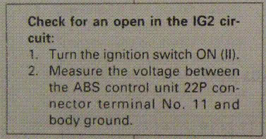
5) Touch the black (negative) multimeter probe to a metal part of the car frame. You should measure approximately "battery voltage". If not, the wire has an open.
1) Set your multimeter to measure voltage. Use the next voltage scale higher than 12V.
2) Touch the red (positive) multimeter probe to the red (positive) battery post and the black multimeter probe to the black (ground) battery post. Note the "battery voltage".
3) Turn the key to ON(II).
4) Locate the wire for terminal 11 on the wire-side of the 22P connector. Use a needle to penetrate the insulation of this wire, and then touch the red (positive) multimeter probe to the needle.
5) Touch the black (negative) multimeter probe to a metal part of the car frame. You should measure approximately "battery voltage". If not, the wire has an open.
Last edited by Former User; 06-23-2009 at 06:46 AM. Reason: text error corrected
06-23-2009, 02:45 PM
#15
Honda-Tech Member
Join Date: Feb 2001
Location: Eastern, ma, US
Posts: 693
Likes: 0
Received 0 Likes
on
0 Posts
That procedure worked flawlessly. I determined that there was voltage at the wire. I attempted to erase the ABS code and this time it worked. And, it didn't come back. So apparently problem is solved for now.
Thanks!
Thanks!
06-25-2009, 05:14 AM
#16
Honda-Tech Member
Join Date: Feb 2001
Location: Eastern, ma, US
Posts: 693
Likes: 0
Received 0 Likes
on
0 Posts
Well, something's still going on. The ABS light came on this morning. Here's what's interesting. If I jump the SCS, I get a code - it went fast and was either 15 or 16. And then instead of the code repeating, the the ABS light stayed on.
So I followed the procedure to erase the code: held down the brake pedal, keyed the ignition on. ABS light comes on then goes off (so far so good). I take my foot off the brake and the ABS light never comes back on (according to the erase instuctions, it should).
And the ABS light doesn't come back on under any circumstances now. This is what happened the other night when I checked the wire voltage. Strange.
06-25-2009, 07:12 AM
#17
Well, something's still going on. The ABS light came on this morning. Here's what's interesting. If I jump the SCS, I get a code - it went fast and was either 15 or 16. And then instead of the code repeating, the the ABS light stayed on.
So I followed the procedure to erase the code: held down the brake pedal, keyed the ignition on. ABS light comes on then goes off (so far so good). I take my foot off the brake and the ABS light never comes back on (according to the erase instuctions, it should).
And the ABS light doesn't come back on under any circumstances now. This is what happened the other night when I checked the wire voltage. Strange.
So I followed the procedure to erase the code: held down the brake pedal, keyed the ignition on. ABS light comes on then goes off (so far so good). I take my foot off the brake and the ABS light never comes back on (according to the erase instuctions, it should).
And the ABS light doesn't come back on under any circumstances now. This is what happened the other night when I checked the wire voltage. Strange.
06-25-2009, 07:54 AM
#19
Honda-Tech Member
Join Date: Feb 2001
Location: Eastern, ma, US
Posts: 693
Likes: 0
Received 0 Likes
on
0 Posts
Agreed. 15 was the code I was getting before which is the right rear sensor. I drove the ITR to work today (a rarity) and so far no codes. Should it come back, I'll check the sensor again.
07-29-2009, 06:32 PM
#20
New User

Join Date: Jul 2009
Posts: 4
Likes: 0
Received 0 Likes
on
0 Posts
08-05-2009, 07:30 AM
#21
Honda-Tech Member
Join Date: Feb 2001
Location: Eastern, ma, US
Posts: 693
Likes: 0
Received 0 Likes
on
0 Posts
08-07-2009, 09:32 AM
#22
Honda-Tech Member
Join Date: Jun 2005
Location: South Charleston, WV, United States
Posts: 682
Likes: 0
Received 0 Likes
on
0 Posts
Im not getting voltage from A21 or A22 therefore no spark. When I crank the car its showing 1.4 volts on both. Any ideas what might cause this or what is keeping it from getting voltage? Thanks.

Thread
Thread Starter
Forum
Replies
Last Post
lsjon
Engine Management and Tuning
3
05-30-2008 08:41 AM
_HANS
Honda Civic / Del Sol (1992 - 2000)
3
06-13-2004 03:33 PM