
C101 and C136 Connector diagrams for patchy

 01-20-2015, 08:52 PM
#27
B*a*n*n*e*d
iTrader: (15)

Join Date: Jul 2008
Location: montebello, ca, us
Posts: 6,632
Likes: 0
Received 15 Likes
on
10 Posts
So to update this problem i was having: it was definitely the key switch
I was going to try and sand the contacts on my old one but i dropped it and springs flew everywhere. I ran to the junkyard and pulled two off a civic and delsol both are the same
I installed it and checked the resistance and read 0 just like it should across the supply voltage wire and acc wire ( blk wht and blk yllw)
Now i just gotta redo my engine harness and i should be good to go
01-21-2015, 01:20 PM
#28
Honda-Tech Member
Join Date: Nov 2007
Location: Western Hemisphere
Posts: 655
Likes: 0
Received 0 Likes
on
0 Posts
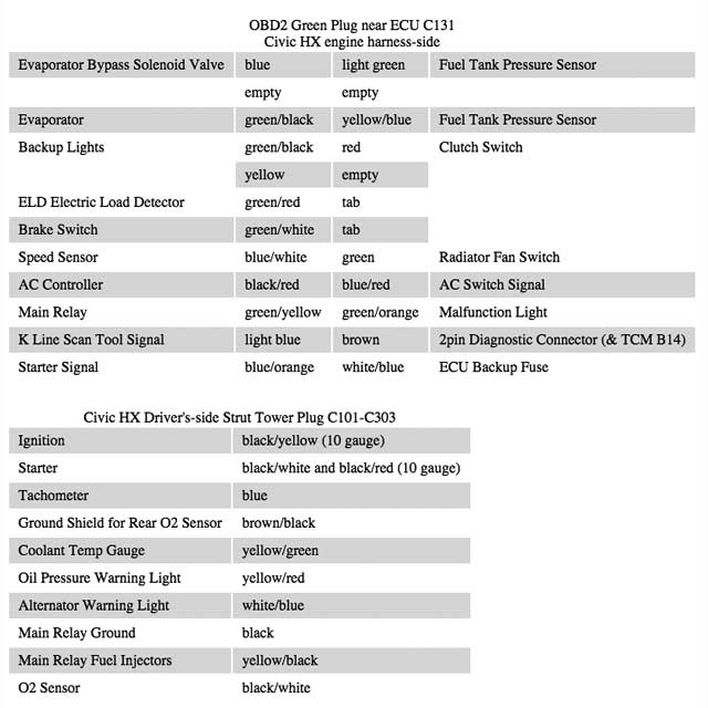
Just to warn you, the official pinouts that were posted (post 1, C101 and post 23, C131) are completely unhelpful and downright wrong. Here are the correct pinouts as I have physically verified by dissecting the engine and dash harnesses by hand:
This in no way reflects on the person who was helpfully sharing the official (albeit inaccurate) documentation
This in no way reflects on the person who was helpfully sharing the official (albeit inaccurate) documentation
Last edited by baller status; 01-21-2015 at 01:44 PM.
01-21-2015, 01:25 PM
#29
Honda-Tech Member
Thread Starter
 01-21-2015, 01:33 PM
#30
Honda-Tech Member
Join Date: Nov 2007
Location: Western Hemisphere
Posts: 655
Likes: 0
Received 0 Likes
on
0 Posts
 01-21-2015, 01:55 PM
#31
Honda-Tech Member
Thread Starter
No offense, but I'm still skeptical.
So what exactly was incorrect in the pin outs?
What year and transmission HX did your wire harnesses come from?
So what exactly was incorrect in the pin outs?
What year and transmission HX did your wire harnesses come from?
01-21-2015, 02:14 PM
#32

I am trying to understand what are the errors. Different years and whether it is A/T or M/T affects the wiring color and whether there is a wire at the cavity.
01-21-2015, 02:17 PM
#33
Honda-Tech Member
Thread Starter
You need to read the pin out diagrams very carefully.
tech8, do you have access to AllDATA?
 01-21-2015, 02:37 PM
#36
It's secured info.
I haven't looked at all the diagrams you posted in this thread; but, I do not see any inaccuracies in what I briefly looked at. Yes, Honda info. can contain errors (like anything); but, I don't find anything materially inaccurate here.
I haven't looked at all the diagrams you posted in this thread; but, I do not see any inaccuracies in what I briefly looked at. Yes, Honda info. can contain errors (like anything); but, I don't find anything materially inaccurate here.
01-22-2015, 02:52 PM
#38
Honda-Tech Member
Join Date: Nov 2007
Location: Western Hemisphere
Posts: 655
Likes: 0
Received 0 Likes
on
0 Posts
Mine applies specifically to the 96-00 HX MT. The difference between the Y5 and Y7/Y8 that is the rear O2 sensor comes out of C131 instead of over by the front O2. 99-00 and other variations aren't different in any way that matters to us.
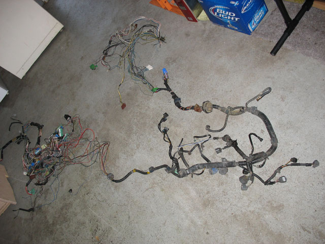
I posted the pic to show that I tore the harnesses down and physically followed each wire to its conclusion. I put a D16Y5 into a CRX, fully converted to OBD2 with an OBD2 scan port and SCS port. It passes safety and emissions (twice now) and has been daily driven by the owner for over a year. No CEL. It throws a code for fuel tank pressure sensor which the CRX does not have, but it doesn't go into limp mode for that. Trouble code but no CEL.
Compare my tables to the official documentation. 13 out of 22 pins on the C131 say "PGM-FI". That sounds fun. How shall I connect a wire to Programmed Multi Port Fuel Injection? Might as well say "car".
Examples of unhelpful info on the C101:
"Fuse 15"
"(G101)"
"(PGM-FI)"
"Charging system"
"Gauges"
"Ignition system"
"Starting system"
Mine which tells you what the wire is coming from or where it needs to go. Try doing a conversion with the official pinouts - I did.
The tables I posted aren't completely finished yet, but the info there is 100% accurate.
01-22-2015, 02:57 PM
#39
Honda-Tech Member
Thread Starter
None taken, none given.
Mine applies specifically to the 96-00 HX MT. The difference between the Y5 and Y7/Y8 that is the rear O2 sensor comes out of C131 instead of over by the front O2. 99-00 and other variations aren't different in any way that matters to us.
I posted the pic to show that I tore the harnesses down and physically followed each wire to its conclusion. I put a D16Y5 into a CRX, fully converted to OBD2 with an OBD2 scan port and SCS port. It passes safety and emissions (twice now) and has been daily driven by the owner for over a year. No CEL. It throws a code for fuel tank pressure sensor which the CRX does not have, but it doesn't go into limp mode for that. Trouble code but no CEL.
Compare my tables to the official documentation. 13 out of 22 pins on the C131 say "PGM-FI". That sounds fun. How shall I connect a wire to Programmed Multi Port Fuel Injection? Might as well say "car".
Examples of unhelpful info on the C101:
"Fuse 15"
"(G101)"
"(PGM-FI)"
"Charging system"
"Gauges"
"Ignition system"
"Starting system"
Mine which tells you what the wire is coming from or where it needs to go. Try doing a conversion with the official pinouts - I did.
The tables I posted aren't completely finished yet, but the info there is 100% accurate.
01-26-2015, 10:17 AM
#40
B*a*n*n*e*d
iTrader: (15)
Join Date: Jul 2008
Location: montebello, ca, us
Posts: 6,632
Likes: 0
Received 15 Likes
on
10 Posts
Ok ron i got another one for you
Do you know or does the book show anywhere how much current some of the sensors draw?
Based off the stock sizing of the wiring i would think not much. Im going to be adding in some deutsch connectors and need to know if i can get away with the smaller pins which is rated for 7.5a or if i need to get the regular sized pins and connectors
01-26-2015, 11:06 AM
#42
B*a*n*n*e*d
iTrader: (15)
Join Date: Jul 2008
Location: montebello, ca, us
Posts: 6,632
Likes: 0
Received 15 Likes
on
10 Posts
Im going to be using 2 12 pin dt connectors to split the harness in half
So all my wiring will be going through those except for the starter signal wire. I might put a small relay in the engine bay and trigger the signal wire with another smaller gauge wore just to keep them all in the same connectors iono yet
So all my wiring will be going through those except for the starter signal wire. I might put a small relay in the engine bay and trigger the signal wire with another smaller gauge wore just to keep them all in the same connectors iono yet
01-26-2015, 11:07 AM
#43
B*a*n*n*e*d
iTrader: (15)
Join Date: Jul 2008
Location: montebello, ca, us
Posts: 6,632
Likes: 0
Received 15 Likes
on
10 Posts
Im going to be using 2 12 pin dt connectors to split the engine harness in half
So all my engine wiring will be going through those connectors except for the starter signal wire.
I might put a small relay in the engine bay and trigger the signal wire with another smaller gauge wore just to keep them all in the same connectors iono yet
So all my engine wiring will be going through those connectors except for the starter signal wire.
I might put a small relay in the engine bay and trigger the signal wire with another smaller gauge wore just to keep them all in the same connectors iono yet
01-26-2015, 01:50 PM
#44
Honda-Tech Member
Thread Starter
Im going to be using 2 12 pin dt connectors to split the harness in half
01-26-2015, 03:21 PM
#45
B*a*n*n*e*d
iTrader: (15)
Join Date: Jul 2008
Location: montebello, ca, us
Posts: 6,632
Likes: 0
Received 15 Likes
on
10 Posts
The engine harness.
All the wiring that goes to the engine?
I dont know what youre trying to say.
I tried makin sense of that diagram the other member posted for the green connector but it doesnt really make any sense. I wrote down all the locations before but i lost it
Heres a pic
 01-26-2015, 08:16 PM
#47
Honda-Tech Member
Thread Starter
Do you know what connector or its location? It seems to be a 22P connector. Okay C131.
Yes, you identified all the pins correctly.
Yes, you identified all the pins correctly.
Last edited by Former User; 01-26-2015 at 08:46 PM.
01-26-2015, 08:42 PM
#48
B*a*n*n*e*d
iTrader: (15)
Join Date: Jul 2008
Location: montebello, ca, us
Posts: 6,632
Likes: 0
Received 15 Likes
on
10 Posts
yea c131
I jus went back to the last pageand seen tech8 posted a pic, I was looking at the pther guys pic it looks like I got it all in the right spots
I jus went back to the last pageand seen tech8 posted a pic, I was looking at the pther guys pic it looks like I got it all in the right spots
01-28-2015, 12:01 PM
#50
Honda-Tech Member
Join Date: Nov 2007
Location: Western Hemisphere
Posts: 655
Likes: 0
Received 0 Likes
on
0 Posts
Disregard my info if it offends you.

