
[DIY] Honda Civic 92-95 JDM "Door Open" Gauge Cluster Indicator Light Install
 01-20-2010, 12:25 AM
#1
[DIY] OEM Honda Civic 92-95 JDM "Door Open" Gauge Cluster Indicator Light Install
OEM JDM 5th Generation Honda Civic tachometer with door-open indicator light to be retrofit into a
CDM 1994 Civic gauge cluster.
Major Updates
JULY/2014: Sources for 6- and 7-pin connectors.
DEC/2013: Updates to diagram and finalized proper wiring.
Introduction
No Canadian Domestic Market (CDM), US Domestic Market (USDM), or European Domestic Market (EDM) 1992-1995 Honda Civics had a gauge cluster light that indicates if the door is open when the vehicle is on. The only way to know is to notice if the dome light is ON, or else as you begin driving you notice there's 10x more road noise in the cabin. Not ideal. Presumably this is due to the Civic's position in the market as a "low-end" vehicle and not worthy of more "higher-end" options. Most or all other vehicles in the Honda/Acura line in the early/mid-90s had some sort of door-open indicator - sometimes this is in the form of just a single light (like on the Integra) or a light that indicates which door is open (Accord, Odyssey).
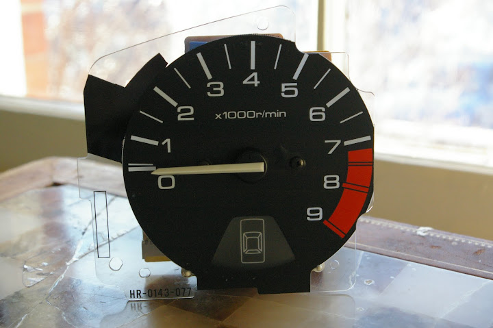
This isn't the case, however, for our friends in the homeland ... Japan that is. Starting at least with the 4th Generation EF9 models, the top-end Civics in Japan began sporting door open indicators in the gauge cluster. This continued into the 5th Generation, where many of you are likely familiar with the EG9 white-face cluster with the door open indicator at the base of the tachometer, as shown in Figure 1.
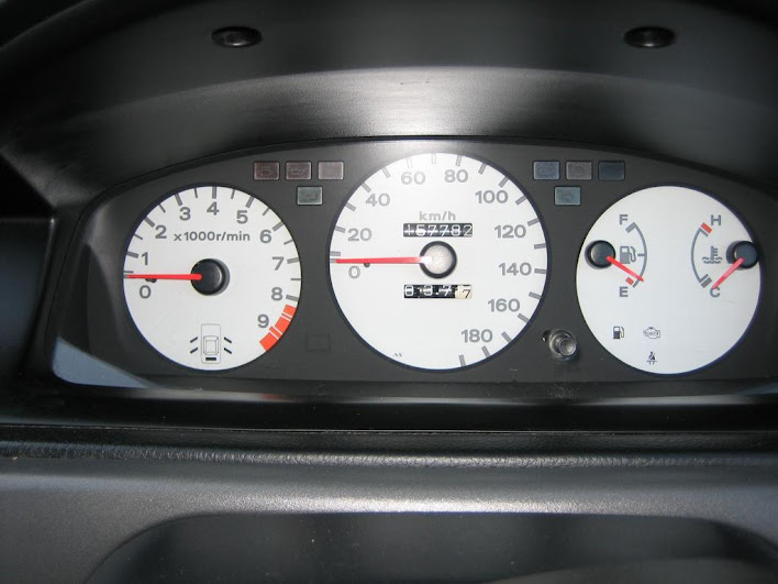
Figure 1. Typical JDM Civic 4dr EG9 Ferio white-faced gauge cluster, with door-open indicator under tachometer.
This actually isn't too notably special because most JDM 4dr Ferio Sedans ALSO got black-faced gauges with door-open indicators in the same location. See Figure 2.
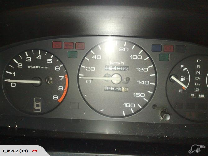
Figure 2. Typical JDM Civic 4dr EG Sedan gauge cluster with door-open indicator. (Note this cluster is from a 4WD EH1 RTX Sedan - cool)
What IS interesting, and pretty rare, is the JDM EG6 3dr Hatchback white-faced gauge cluster with door-open indicator (Figure 3). From my research, it seems that these were only available in 1995? Possibly 1994? Anyway, suffice to say that you more often see them without the indicators, suggesting to me that only a minority of EG6s got this feature. I've only seen them with the TCS (Traction Control System) feature on them, too.
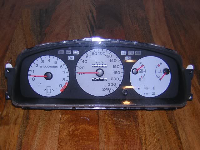
Figure 3. Rarer JDM Civic 3dr EG6 Hatchback gauge cluster with door-open indicator (and TCS). Possibly only seen in 1995. Also, it has a 250km/h speedo! This is likely a Spoon piece.
I've never seen anyone take an interest in actually getting these indicators to work properly on our 5th Gen Civics. There's this link over at poor old e-hatch.com, showing the circuit board, but it is just providing instructions on getting the trunk/rear hatch light to function and makes no mention of the doors.
I'm interested in adding OEM features to my vehicle - especially ones that add function and practicality, so this write-up describes the process of adding the tachometer with FUNCTIONING door-open indicator to my CDM 1994 Civic CX Hatchback. To begin, note that I am NOT interested in the white-faced gauges. These, to me, have decreased functionality as they do not have: 1. Km/h AND mph markings; 2. Cruise Control indicator light (since I added CC to my CX); 3. TCS indicator features which I will never use and don't want to stare at. However, it DOES have a low fuel indicator, which is nice. (LINK to my low-fuel sender DIY.) The other features which make them "different" (orange needles, amber glow, white faces) just really aren't that interesting to me, and might frankly be a little played out. I might consider it at some future date when I can design my own gauge faces.
So, while technically no JDM EG3/EG4/EG5 hatchbacks with black-faced gauges got a door open indicator that I'm aware of, the fact that an EG6 got it in some form provided reason enough to perform the retrofit on my own vehicle. Following this DIY, you'll get a final product that resembles Figure 4:

Figure 4. JDM tachometer with door-open indicator transplanted into CDM gauge cluster. Sorry about the shyte photo. I'll take a better one some day.
Note that this write-up pertains specifically to modifications to a 5th Generation 92-95 3DR Honda Civic Hatchback. The instructions will be the identical for a 5G Coupe. I will do my best to provide DIY modifications that will translate to a 4DR Sedan - I believe the only difference is the requirement to run independent wires to the rear doors.
Preparation
Notes on wiring
Connecting and installing the wiring properly will likely take you the most time out of all the operations involved in this project. I haven't hack-jobbed or jerry-rigged anything in this write-up - I firmly believe that this is about as close to a clean OEM retrofit as you can get.
My recommendation is, and if you're like me and want as clean an install as possible, you will spend time pulling the correct colour of wires from a salvage yard vehicle. This guide will tell you where to find the colour of wires in a 92-95 Civic to match the OEM colours.
Extracting the wiring harnesses -- while painful -- makes the re-wiring exercise considerably more pleasant, gives you the exact OEM wire colours, and means you don't have to go out and buy your OWN wire.
Wiring Connectors
When you do have to patch together cut wires, I recommend using Bullet connectors. These attach & detach readily and are self-shielding. I suppose a cautious person would electrical-tape all the connections, but I didn't. As I am in Canada, I purchased my electronics parts over the phone from A-1 Electronics - see http://www.a1parts.com/ (WARNING: TERRIBLE WEBSITE. GODAWFUL.); these had the best prices around Canada that I could find, and domestic shipping was a flat $10. A long time ago I ordered a pack of 100 for each of Male & Female 14-16 (blue) & 16-18 (red) gauge Bullet connectors, and a pack of 100 of each of 14-16 (blue) & 16-18 gauge wire-taps (T-Taps), and they are still serving me well. This amount might be overkill for you, but I had a bunch of projects I wanted to wire up so it was a good investment for me.
Americans can just look on eBay; there's dozens of dealers selling large bulk packs of bullet connectors.
Pin Removal
You'll have to do a bit of this. A tiny screwdriver is your friend. Look up on honda-tech.com the correct way to remove pins from connectors, or consult this comprehensive guide.
Note on Order of Operations
The instructions, as written below, aren't necessarily meant to be followed linearly as a step-by-step process of removal and then re-installation. Read the whole thing through, first, to get an idea of what you're up against. You will have to jump around a bit from section to section as you see fit. There is no real "wrong" order to do the install, but you will run in to obvious roadblocks, in which case you'll have to figure out on your own what a logical order to proceed is.
Project Difficulty and Time Commitment
This project is not difficult, especially if you can read a wiring diagram. Expect to spend a day foraging for the wires in the salvage yard. It took me about a day to rewire the parts necessary to get the door-open indicators to work. Expect it to take the equivalent of 1-2 days of work to install. A cautious person would plan to have their vehicle out of commission for two days just in case something goes wrong.
Disclaimer
Or, "Don't point fingers, you only have yourself to blame"
Every effort has been made to make these instructions as complete and accurate as possible, but no warranty or fitness is implied. The information is provided on an �as is� basis. The author(s) and the website/publisher(s) shall have neither liability nor responsibility to any person or entity with respect to any loss or damages or inconvenience arising from the information contained herein, nor due to any omissions. Read: Don't muck up your vehicle and try to blame me or anyone else. You are responsible for your own due diligence and research.
Acknowledgements
I would like to extend my gratitude to H-T user "fungus mungus" who sourced the cluster I used for this DIY. I would be a lot poorer (literally and figuratively) today were it not for his willing assistance while juggling a busy schedule and family.
Parts Required & Removal Instructions
Before you begin
Online

Figure 5a. BROWN circuit board manufactured by Nippon Seiki. The circuitry of this board is essentially the same as CDM/USDM/EDM. Note external module on right, behind tachometer. (1) is 7-pin door- and trunk-open indicator plug. (2) is a 6-pin plug for various TCS stuff. (3) are indicator lights for TCS.

Figure 5b. GREEN circuit board made by DENSO. NOT transferable to a CDM/USDM gauge cluster case.
From the Salvage Yard
Basically, you just need a bit of the correct colour of wiring for this project.
Installation Instructions
Before You Begin
Gauge Cluster
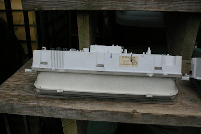
Figure 6a. Normal CDM/USDM cluster (bottom view).

Figure 6b. JDM cluster (bottom view) with access hole at right for wires from door-open indicator external module (module not shown ).
).
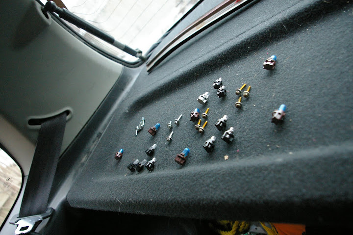
Figure 7. Bulbs and screws removed from a cluster, and laid out in the pattern they are mounted.
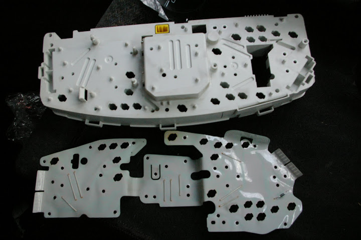
Figure 8a. CDM/USDM gauge cluster circuit board removed from case.
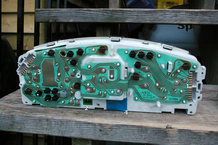
Figure 8b. CDM/USDM gauge cluster circuit board mounted on JDM case. (1) is ADDITIONAL screw for connection to door-open indicator in tach. (2) is Cruise Control plug reinstalled. (3) BE CAREFUL WHEN REINSTALLING SCREWS FOR TEMP AND FUEL GAUGE. DO NOT OVER-TIGHTEN!!! (4) Since my vehicle does not have SRS, I've taken this time to leave off the indicator that was in the original cluster.
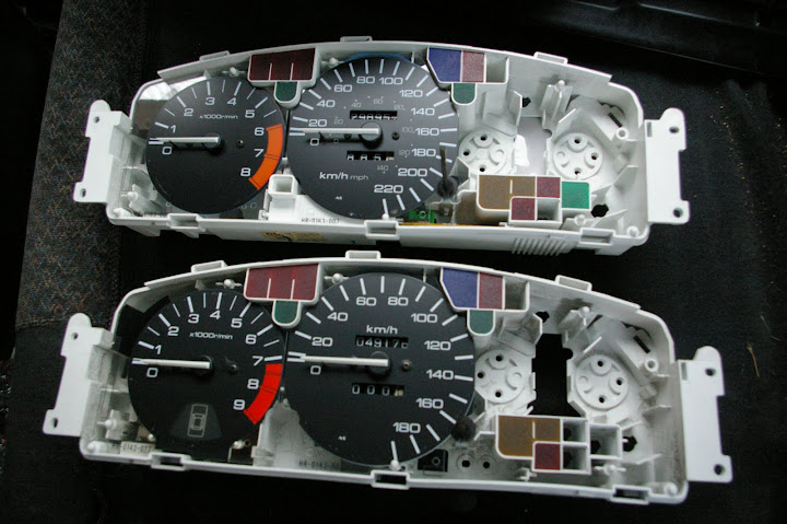
Figure 9a. Swap the coloured plastics where necessary.

Figure 9b. Pull out the tiny bulbs for the rear doors (bottom right of picture).
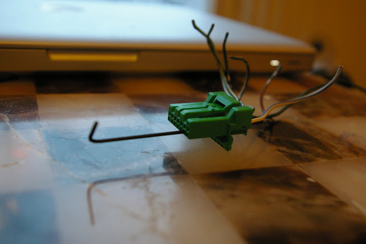
Figure 10a. The 7-pin connector for the external module. Some wire colours need to be swapped to correct for RHD <-> LHD. Use a very small hex key to remove the pins.
Wiring
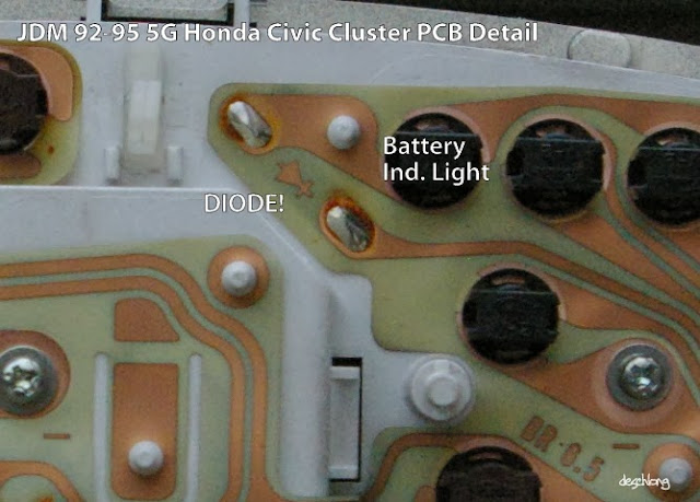
Figure 10b: JDM Cluster PCB detail showing the diode after the battery indicator light.

Figure 10c: CDM/USDM Cluster PCB detail showing NO diode after the battery indicator light. Note the PCB layout is accordingly also slightly different.

Figure 10d: Door-open indicator module wiring for LHD vehicle.
Cabin: Under Dash/Footwell
Wiring
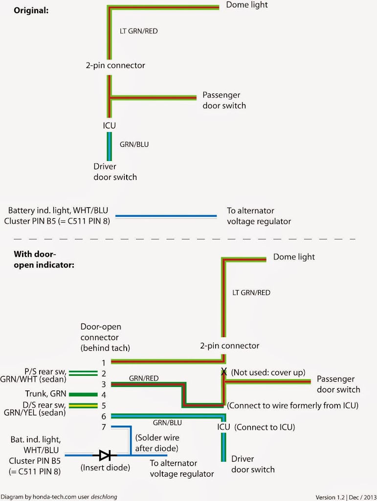
Figure 11 is a wiring diagram that basically shows what's going on in the externally-mounted module. (Courtesy rickbrice.com) Errors in this diagram are noted. Some day I will make a better diagram for a more thorough picture of the circuitry including this module and the circuitry of the door-open indicator on the tach. This will have to do for now, though.
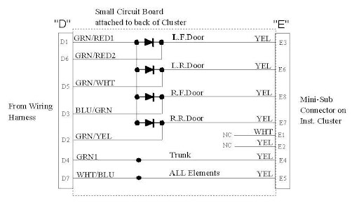
Figure 11. Wiring diagram for the external module (from rickbrice.com). Note: BLU/GRN should read GRN/BLU. GRN/RED1 should read LT GRN/RED for 94/95 vehicles. Wiring reflects existing RHD setup and some wiring is swapped for LHD (see text).
Figure 11a is the wiring diagram from the JDM Service Manual. Unfortunately, it's all in Japanese, but it does help.
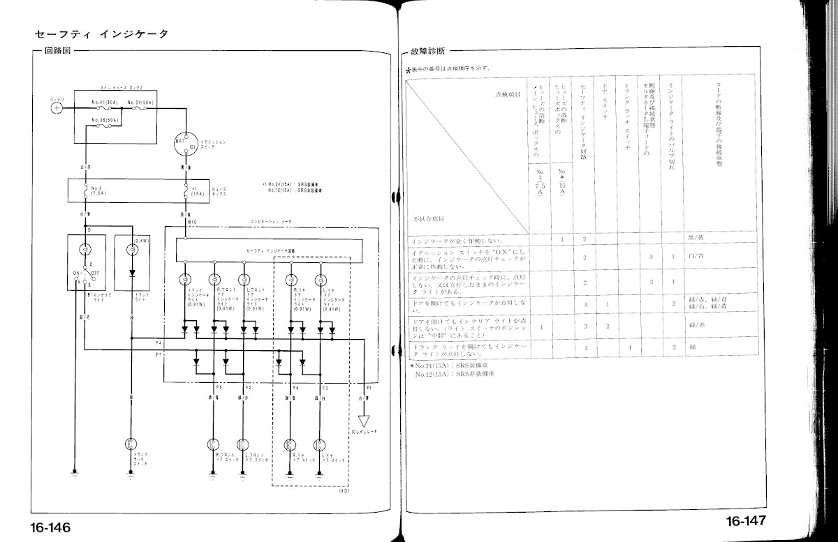
Figure 11a. Pages from the JDM Service Manual explaining door-open indicator wiring.
For a 2/3DR and 4DR:
For a 4DR:
Test Drive

Figure 12. OEM JDM 5th Generation Honda Civic tachometer with door-open indicator light retrofit into a CDM 1994 Civic gauge cluster.
Good Luck, and by every indication, you've made a practical improvement to your ride.
DeSchlong
January, 2010
OEM JDM 5th Generation Honda Civic tachometer with door-open indicator light to be retrofit into a
CDM 1994 Civic gauge cluster.
Major Updates
JULY/2014: Sources for 6- and 7-pin connectors.
DEC/2013: Updates to diagram and finalized proper wiring.
Introduction
No Canadian Domestic Market (CDM), US Domestic Market (USDM), or European Domestic Market (EDM) 1992-1995 Honda Civics had a gauge cluster light that indicates if the door is open when the vehicle is on. The only way to know is to notice if the dome light is ON, or else as you begin driving you notice there's 10x more road noise in the cabin. Not ideal. Presumably this is due to the Civic's position in the market as a "low-end" vehicle and not worthy of more "higher-end" options. Most or all other vehicles in the Honda/Acura line in the early/mid-90s had some sort of door-open indicator - sometimes this is in the form of just a single light (like on the Integra) or a light that indicates which door is open (Accord, Odyssey).
This isn't the case, however, for our friends in the homeland ... Japan that is. Starting at least with the 4th Generation EF9 models, the top-end Civics in Japan began sporting door open indicators in the gauge cluster. This continued into the 5th Generation, where many of you are likely familiar with the EG9 white-face cluster with the door open indicator at the base of the tachometer, as shown in Figure 1.
Figure 1. Typical JDM Civic 4dr EG9 Ferio white-faced gauge cluster, with door-open indicator under tachometer.
This actually isn't too notably special because most JDM 4dr Ferio Sedans ALSO got black-faced gauges with door-open indicators in the same location. See Figure 2.
Figure 2. Typical JDM Civic 4dr EG Sedan gauge cluster with door-open indicator. (Note this cluster is from a 4WD EH1 RTX Sedan - cool)
What IS interesting, and pretty rare, is the JDM EG6 3dr Hatchback white-faced gauge cluster with door-open indicator (Figure 3). From my research, it seems that these were only available in 1995? Possibly 1994? Anyway, suffice to say that you more often see them without the indicators, suggesting to me that only a minority of EG6s got this feature. I've only seen them with the TCS (Traction Control System) feature on them, too.
Figure 3. Rarer JDM Civic 3dr EG6 Hatchback gauge cluster with door-open indicator (and TCS). Possibly only seen in 1995. Also, it has a 250km/h speedo! This is likely a Spoon piece.
I've never seen anyone take an interest in actually getting these indicators to work properly on our 5th Gen Civics. There's this link over at poor old e-hatch.com, showing the circuit board, but it is just providing instructions on getting the trunk/rear hatch light to function and makes no mention of the doors.
I'm interested in adding OEM features to my vehicle - especially ones that add function and practicality, so this write-up describes the process of adding the tachometer with FUNCTIONING door-open indicator to my CDM 1994 Civic CX Hatchback. To begin, note that I am NOT interested in the white-faced gauges. These, to me, have decreased functionality as they do not have: 1. Km/h AND mph markings; 2. Cruise Control indicator light (since I added CC to my CX); 3. TCS indicator features which I will never use and don't want to stare at. However, it DOES have a low fuel indicator, which is nice. (LINK to my low-fuel sender DIY.) The other features which make them "different" (orange needles, amber glow, white faces) just really aren't that interesting to me, and might frankly be a little played out. I might consider it at some future date when I can design my own gauge faces.
So, while technically no JDM EG3/EG4/EG5 hatchbacks with black-faced gauges got a door open indicator that I'm aware of, the fact that an EG6 got it in some form provided reason enough to perform the retrofit on my own vehicle. Following this DIY, you'll get a final product that resembles Figure 4:
Figure 4. JDM tachometer with door-open indicator transplanted into CDM gauge cluster. Sorry about the shyte photo. I'll take a better one some day.
Note that this write-up pertains specifically to modifications to a 5th Generation 92-95 3DR Honda Civic Hatchback. The instructions will be the identical for a 5G Coupe. I will do my best to provide DIY modifications that will translate to a 4DR Sedan - I believe the only difference is the requirement to run independent wires to the rear doors.
Preparation
Notes on wiring
Connecting and installing the wiring properly will likely take you the most time out of all the operations involved in this project. I haven't hack-jobbed or jerry-rigged anything in this write-up - I firmly believe that this is about as close to a clean OEM retrofit as you can get.
My recommendation is, and if you're like me and want as clean an install as possible, you will spend time pulling the correct colour of wires from a salvage yard vehicle. This guide will tell you where to find the colour of wires in a 92-95 Civic to match the OEM colours.
Extracting the wiring harnesses -- while painful -- makes the re-wiring exercise considerably more pleasant, gives you the exact OEM wire colours, and means you don't have to go out and buy your OWN wire.
Wiring Connectors
When you do have to patch together cut wires, I recommend using Bullet connectors. These attach & detach readily and are self-shielding. I suppose a cautious person would electrical-tape all the connections, but I didn't. As I am in Canada, I purchased my electronics parts over the phone from A-1 Electronics - see http://www.a1parts.com/ (WARNING: TERRIBLE WEBSITE. GODAWFUL.); these had the best prices around Canada that I could find, and domestic shipping was a flat $10. A long time ago I ordered a pack of 100 for each of Male & Female 14-16 (blue) & 16-18 (red) gauge Bullet connectors, and a pack of 100 of each of 14-16 (blue) & 16-18 gauge wire-taps (T-Taps), and they are still serving me well. This amount might be overkill for you, but I had a bunch of projects I wanted to wire up so it was a good investment for me.
Americans can just look on eBay; there's dozens of dealers selling large bulk packs of bullet connectors.
Pin Removal
You'll have to do a bit of this. A tiny screwdriver is your friend. Look up on honda-tech.com the correct way to remove pins from connectors, or consult this comprehensive guide.
Note on Order of Operations
The instructions, as written below, aren't necessarily meant to be followed linearly as a step-by-step process of removal and then re-installation. Read the whole thing through, first, to get an idea of what you're up against. You will have to jump around a bit from section to section as you see fit. There is no real "wrong" order to do the install, but you will run in to obvious roadblocks, in which case you'll have to figure out on your own what a logical order to proceed is.
Project Difficulty and Time Commitment
This project is not difficult, especially if you can read a wiring diagram. Expect to spend a day foraging for the wires in the salvage yard. It took me about a day to rewire the parts necessary to get the door-open indicators to work. Expect it to take the equivalent of 1-2 days of work to install. A cautious person would plan to have their vehicle out of commission for two days just in case something goes wrong.
Disclaimer
Or, "Don't point fingers, you only have yourself to blame"
Every effort has been made to make these instructions as complete and accurate as possible, but no warranty or fitness is implied. The information is provided on an �as is� basis. The author(s) and the website/publisher(s) shall have neither liability nor responsibility to any person or entity with respect to any loss or damages or inconvenience arising from the information contained herein, nor due to any omissions. Read: Don't muck up your vehicle and try to blame me or anyone else. You are responsible for your own due diligence and research.
Acknowledgements
I would like to extend my gratitude to H-T user "fungus mungus" who sourced the cluster I used for this DIY. I would be a lot poorer (literally and figuratively) today were it not for his willing assistance while juggling a busy schedule and family.
Parts Required & Removal Instructions
Before you begin
- Note that some wire colours for the courtesy (dome) light changed for the years 94/95 from 92/93. Mainly, it appears that the wire colour returning from the dome light was changed from GRN/RED to LT GRN/RED. Also, it's possible the colour of the wire going to the dome light from the under-dash fuse box was changed from WHT/BLU to WHT/RED, but we're not really interested in that wire in this write up. I will refer to LT GRN/RED in this DIY, but if your vehicle is a 92/93, know that this wire may be coloured differently.
Online
- The hunt begins online for a JDM gauge cluster. Ebay is probably your best source. If you're after the white-faced gauges, try to get the one with the correct number of doors, otherwise it just looks funny and wrong. If you're interested in the black-faced gauges, it doesn't matter if you have a 2/3DR or 4DR vehicle because you can't see the door indicators if they're not lit up. I show you in this DIY how to eliminate the extra indicators for doors that are not used.
- Whatever you do, before you buy, make sure you see a photo of the BACK of the cluster. There are two JDM styles: One made by Nippon Seiki with a BROWN circuit board (Figure 5a) on the back, and another made by DENSO with a GREEN circuit board (Figure 5b). IMPORTANT: ONLY THE CLUSTER WITH THE BROWN CIRCUIT BOARD WILL BE COMPATIBLE WITH YOUR CDM/USDM CLUSTER, if you're going to be swapping the tach/door-open indicator into your existing cluster. You'll see what I mean below.
- ALSO IMPORTANT: YOU WANT THE PIGTAILS! AT MINIMUM, YOU WANT THE 7-PIN ONE ON THE EXTERNAL MODULE SEEN IN FIGURE 5a. This plug is DIFFICULT to find in North America and Europe. It is a 7-pin plug design that I have never seen before on any other vehicle, though you're welcome to look around and post back here.
- UPDATE JUL/2014: These 6- and 7-pin connectors have been tracked down in other Honda vehicles by user kmankd. Check out his excellent post later in this DIY thread here.
- UPDATE SPRING/2014: The user 'HiTec' has located another device that has a compatible 7-pin plug - this was on a JDM Prelude Power Folding Mirror Relay. See his post on the next page.) The TCS plug is 6-pin and should also be very hard or impossible to find.
- UPDATE WINTER/2012: I have seen this 6-pin connector on the dash harness of a del Sol.
- If you don't get these plugs then you are going to have to hard-wire (solder) your wiring directly to the external module and this is not a clean install. Just better wait until you can find a cluster with the pigtails or scrounge them from other Hondas.
- UPDATE DEC/2013: You need to add a diode. Pillage this from the back of just about any CDM / USDM cluster - you'll see it used for the existing trunk-open indicator. (You can even use the one on your existing cluster, since you're moving that indicator anyway, if you're feeling really confident!) Otherwise hop online and get some from China. I bought http://www.ebay.com/itm/10pcs-GW-Good-Work-Rectifier-SB560-Diode-RoHS-Lead-Free-5A-5AMP-40V-BRAND-NEW-/220883252716?hash=item336daaf5ec (if link is dead, search eBay for: "SB560 Diode 5A 5AMP 40V") and they are serious overkill for this application, but they work fine, so whatever.
 These are also useful if you are ever planning on doing your own security system installation.
Figure 5a. BROWN circuit board manufactured by Nippon Seiki. The circuitry of this board is essentially the same as CDM/USDM/EDM. Note external module on right, behind tachometer. (1) is 7-pin door- and trunk-open indicator plug. (2) is a 6-pin plug for various TCS stuff. (3) are indicator lights for TCS.
Figure 5b. GREEN circuit board made by DENSO. NOT transferable to a CDM/USDM gauge cluster case.
From the Salvage Yard
Basically, you just need a bit of the correct colour of wiring for this project.
- For a 2/3DR and 4DR:
- Basically, all you need from the salvage yard is a couple of lengths of wire of the right colour. About 2-3ft of each of the following colours should work.
- LT GRN/RED: Runs from a connector for the dome light wire under your dash to the gauge cluster. Your options for sources are:
- 94/95: Remove from the dome light wiring. You'll need a female connector pin on one end.
- 92-95 w/cruise: runs from the cruise brain to the slip ring on steering column (CDM w/cruise & non-SRS) or the under-dash connection for the clock spring (CDM/USDM w/cruise & SRS).
- GRN/RED: Runs from the gauge cluster to the front passenger side door switch (though it's possible just to connect it back up to LT GRN/RED under-dash). Your options for sources are:
- 92/93: Remove from the dome light wiring.
- 92-95: Runs along the door sill between the door and the driver's seat (under the carpet).
- Optional: Get enough to run all the way from the under-dash fuse box to the front passenger side door switch, as this is likely the OEM JDM wiring colours.
- GRN/BLU: Runs from the gauge cluster to the Integrated Control Unit (ICU) on the back of the under-dash fuse box. From here, a GRN/BLU already runs to the front driver's side door switch. Your options for sources are:
- 92-95: Obviously, you can find it running along the door sill between the door and the driver's seat (under the carpet). You'll need a female connector pin on one end.
- LT GRN/RED: Runs from a connector for the dome light wire under your dash to the gauge cluster. Your options for sources are:
- Basically, all you need from the salvage yard is a couple of lengths of wire of the right colour. About 2-3ft of each of the following colours should work.
- For a 4DR:
- Additionally, you'll need wires that run all the way from the gauge cluster to the right and left rear passenger doors. The colours for these wires are GRN/YEL for the left (driver's side) rear passenger door, and GRN/WHT for the right side. By convention, Honda seems to re-use these same colours to the door switches for many of its different models. So, you should be able to source these wire colours from a mid-90s Accord or Odyssey, as these vehicles both had independent door open indicators for each door. In fact, you could do that for the wiring colours above, too.
- UPDATE DEC/2013: I found it easier to make a little interconnect harness for the dome light wire connection instead of messing around with the pins. WAY faster to install. If you're looking for the right connectors to do this, pillage both male AND female connectors for the seat belt wiring under the driver's seat of a junkyard vehicle.
Installation Instructions
Before You Begin
- Remove the negative cable of your battery before performing any electrical work on your vehicle.
- My car doesn't have SRS, but I take it they can blow up in your face, so take necessary precautions to disable. Your Helms manual is explicit in this regard.
Gauge Cluster
- If you're swapping the JDM tach into your existing CDM/USDM one, then the first thing you need to do is swap the entire circuit board from your existing cluster to the JDM case. This is done to retain the functionality of the dimmer (JDM and EDM clusters DON'T DIM), and mainly to use the case with the access hole in the bottom (Figure 6a & 6b).
Figure 6a. Normal CDM/USDM cluster (bottom view).
Figure 6b. JDM cluster (bottom view) with access hole at right for wires from door-open indicator external module (module not shown
). -
- CLARIFICATION: So, originally I thought I could just install the external module onto the back of my CDM cluster, and put the tach/door-open indicator inside it and be done. However, I didn't know that the design of the JDM case was different with the small access hole for the wires, so I swapped the whole CDM circuit board onto the JDM one. If you don't care about dimmer functionality, then I suppose you can skip this step. However, I still did it to make it a more "authentic" merger of the different functions of CDM/USDM and JDM clusters.
- This is pretty easy to do. First remove the external module. I pops off its pegs and the wires disconnect. Then I took all the screws and bulbs out and laid them out in the same pattern as how I removed them (Figure 7). Then you slowly and methodically pry the board off its pegs. A small screwdriver helped lift it up. WORK SLOWLY. The board will come off completely, and can be remounted on the other case. (Figure 8a and 8b).
- Also, don't forget the FOURTH additional screw that goes into the back of the tach. (Figure 8b.) This routes power from BLK/YEL to the door-open indicator.
- Don't forget to swap the coloured plastics on the inside! (Figure 9a.) I had to swap the large green square for the CC indicator. I also swapped the red square for the "trunk open" indicator, even though I won't be using this feature anymore on the new set-up. This is redundant as the tach-mounted door-open indicator also has a trunk open indicator.
- Transfer the little CC indicator light module.
- WARNING: DO NOT OVER-TIGHTEN THE SCREWS. Especially for the fuel and temp gauges. Stop tightening when you begin to feel resistance. There is a chance that you will wreck the gauge. I've done this before and it is NOT A FUN REPAIR. YOU HAVE BEEN WARNED. HEED THIS INFORMATION AT YOUR OWN PERIL OR MANY TEARS WILL BE SHED BY YOU AND YOU WILL HATE YOURSELF WITH THE INTENSITY OF A THOUSAND SUNS.

Figure 7. Bulbs and screws removed from a cluster, and laid out in the pattern they are mounted.
Figure 8a. CDM/USDM gauge cluster circuit board removed from case.
Figure 8b. CDM/USDM gauge cluster circuit board mounted on JDM case. (1) is ADDITIONAL screw for connection to door-open indicator in tach. (2) is Cruise Control plug reinstalled. (3) BE CAREFUL WHEN REINSTALLING SCREWS FOR TEMP AND FUEL GAUGE. DO NOT OVER-TIGHTEN!!! (4) Since my vehicle does not have SRS, I've taken this time to leave off the indicator that was in the original cluster.
Figure 9a. Swap the coloured plastics where necessary.
- UPDATE DEC/2013: I swapped this cluster over to another vehicle in December 2012. Before I did this, I pulled the tach piece apart to see how it worked, and to try to answer some outstanding questions. But, basically since this cluster was pulled from a 4dr Sedan and is being mounted in a 3dr Hatch, it is necessary to remove two bulbs that act as the indicators for the rear doors, if I wanted full functionality and have the bulbs turn on at key position IG1 (see below). This is an easy step and the bulbs just pull right out once you get access to them (Figure 9b).
Figure 9b. Pull out the tiny bulbs for the rear doors (bottom right of picture).
- You need to switch around some wires in the 7-pin external module connector. This is because the connector is meant for an RHD vehicle, so on an LHD the colours for the "Driver" and "Passenger" doors are reversed. Swap GRN/BLU with GRN/RED, and swap GRN/WHT with GRN/YEL. Do this using the smallest, smallest hex key you can find! Open the retainer on the connector then insert the hex key into the hole above the pin, as in Figure 10a. Push it in, you will feel some resistance.... push it in a little more... you might feel a little 'click'. Pull out the wire.
Figure 10a. The 7-pin connector for the external module. Some wire colours need to be swapped to correct for RHD <-> LHD. Use a very small hex key to remove the pins.
Wiring
- GRN: You have to remove one pin for your trunk indicator from your existing cluster plug to re-route to the new tach.
- This is a GRN wire on the "A" plug (behind fuel/temp gauge) at position 2 (ie., pin A2). I didn't cut this wire... I put a female bullet connector on the wire from the 7-pin external module connector, and slid the existing pin into the bullet connector. Taped it up with electrical tape and considered it done. (It also means it is easily fully reversible.)
- LT GRN/RED, GRN/BLU, GRN/RED (4DR: GRN/WHT, GRN/YEL): Connect to 7-pin module pigtail. Cover up any unused wires.
- WHT/BLU: On the 7-pin connector, there's a WHT/BLU wire. UPDATE DEC/2013: This wire routes power from the gauge cluster through ALL of the door- and trunk-open indicator lights. It comes on while the key is in ON (IG1), and ALL the door- and trunk-open indicator lights turn on. This tests the indicator bulbs to show that they are working. It's the same principle that's tied to the BAT light that comes on at position ON (IG1), and in fact uses the same wire.
- The reason you need to do this step is because the PCB on the JDM cluster has this diode integrated already and the CDM/USDM one does not (Figures 10b and 10c). This diode is necessary for this feature to function.
- To get this to work properly, you need to add a diode AFTER WHT/BLU emerges from the cluster connector B5 (= C511 PIN 8) IF you swapped PCBs over as I detailed above. You are essentially mimicking the functionality of the JDM PCB but we are forced to do this along the wire instead of within the PCB. CUT the wire and solder in the diode. I put mine oh about 3 to 5cm after it exits the cluster. The diode direction (the little line on it) is pointing AWAY from the cluster. Connect WHT/BLU from the door-open connector here, AFTER the diode. To make things simple you can solder both wires together here right after the diode - meaning, the new WHT/BLU from the door-open connector and the existing WHT/BLU that you cut plus the wire from the end of the diode can all three be soldered together. See the simplified wiring diagram at the end of this DIY for a visual of this.
- The reason you need to do this step is because the PCB on the JDM cluster has this diode integrated already and the CDM/USDM one does not (Figures 10b and 10c). This diode is necessary for this feature to function.
Figure 10b: JDM Cluster PCB detail showing the diode after the battery indicator light.
Figure 10c: CDM/USDM Cluster PCB detail showing NO diode after the battery indicator light. Note the PCB layout is accordingly also slightly different.
- Here's what the wiring looks like on the back module (Figure 10d), after the wires have been swapped to their correct location for an LHD vehicle.
Figure 10d: Door-open indicator module wiring for LHD vehicle.
Cabin: Under Dash/Footwell
Wiring
Figure 11 is a wiring diagram that basically shows what's going on in the externally-mounted module. (Courtesy rickbrice.com) Errors in this diagram are noted. Some day I will make a better diagram for a more thorough picture of the circuitry including this module and the circuitry of the door-open indicator on the tach. This will have to do for now, though.
Figure 11. Wiring diagram for the external module (from rickbrice.com). Note: BLU/GRN should read GRN/BLU. GRN/RED1 should read LT GRN/RED for 94/95 vehicles. Wiring reflects existing RHD setup and some wiring is swapped for LHD (see text).
Figure 11a is the wiring diagram from the JDM Service Manual. Unfortunately, it's all in Japanese, but it does help.
Figure 11a. Pages from the JDM Service Manual explaining door-open indicator wiring.
For a 2/3DR and 4DR:
- LT GRN/RED: Find the 2-pin connector that routes power from the under-dash fuse box to the dome light. Well, actually, the connector is where the wires to/from the dome come down the A-pillar and meet the wires from the fuse box. You'll find this on the left side of the footwell attached to the body. It's HARD TO SEE. You'll first need to take out the fuse box. If you have Cruise Control, then the connector is just to the rear (towards the back of the car) of the top bolt that holds the cruise brain bracket to the body. I wish I took a pic. Actually, there's an angle while you're on your back in the footwell that you can see the connector directly through the mess of wiring.
- Anyway, you need to undo the connector, and de-pin the LT GRN/RED wire. You do not have much room to manoeuvre. Cover up this wire with electrical tape - you're not going to use it anymore.
- Insert your salvaged LT GRN/RED into this connector and plug it back in to its original place.
- (UPDATE DEC/2013: As mentioned earlier, I found it easier to make a little interconnect harness here instead of messing around with the pins. WAY faster to install. I have lots of spare wiring laying around so it was easy for me to do this. If you're looking for the right connectors to do this, pillage both male AND female connectors for the seat belt wiring under the driver's seat of a junkyard vehicle.)
- GRN/RED: There's an LT GRN/RED wire in the ICU. Remove it and connect your GRN/RED from the gauge cluster to this wire. You can cut the wire and attach a bullet connector, if you want - though I dislike cutting my original vehicle wiring.
- Technically, this LT GRN/RED is the incorrect wire colour. It should technically be substituted with GRN/RED all the way to the passenger's side door switch. I didn't do this because I thought it would be unnecessary plus it's a real pain in the butt.
- GRN/BLU: Insert GRN/BLU into the spot on the ICU where you just removed the LT GRN/RED in the step above.
For a 4DR:
- GRN/YEL: Run this wire to the rear left (D/S) passenger door switch.
- GRN/WHT: Run this wire to the rear right (P/S) passenger door switch.
Test Drive
- Reconnect your fuse box plugs.
- Reconnect your battery.
- Normal operation will involve:
- Turn your ignition to IG1. All bulbs will light up as a test of the circuit. (This is the circuit being grounded through the WHT/BLU wire.)
- Start the car. Open a door. The corresponding door (or trunk) indicator will light up in the cluster (Figure 12).
Figure 12. OEM JDM 5th Generation Honda Civic tachometer with door-open indicator light retrofit into a CDM 1994 Civic gauge cluster.
- If it does not work on the first try, troubleshoot all your connections.
- I wouldn't completely reassemble all your parts before your first test try. Leave off certain pieces of trim to make it easier to troubleshoot if you encounter problems.
Good Luck, and by every indication, you've made a practical improvement to your ride.
DeSchlong
January, 2010
Last edited by deschlong; 07-26-2014 at 12:54 PM. Reason: Updates.

The following users liked this post:
01-20-2010, 12:51 AM
#2
Honda-Tech Member

Join Date: Jan 2010
Location: SA, Texas
Posts: 23
Likes: 0
Received 0 Likes
on
0 Posts
Very nice write up. Thank you for taking the time to put that together.
I'm looking forward to the low fuel light:
I'm looking forward to the low fuel light:
low fuel indicator, which is nice. (I'll also be providing a DIY for a retrofit of this at a future date.)
01-20-2010, 08:56 AM
#3
Thanks!
I'm sure you're not the only one looking forward to that low fuel sensor write-up. I'd imagine everyone that owns a JDM/EDM cluster with that indicator light is wondering how to get it to work. I should be able to get to it this spring as I now have the correct fuel level sender with low fuel sensor from an EG.
I'm sure you're not the only one looking forward to that low fuel sensor write-up. I'd imagine everyone that owns a JDM/EDM cluster with that indicator light is wondering how to get it to work. I should be able to get to it this spring as I now have the correct fuel level sender with low fuel sensor from an EG.
01-20-2010, 10:32 AM
#4
Honda-Tech Member
Glad to see this one finally get done. As always, great job on the write-up!
fm
fm

Trending Topics
04-08-2010, 03:41 PM
#9
Honda-Tech Member
thanks for the pinout diagram DeSchlong. you should do a write up on how to connect the gas light. you gotta change out the fuel pump ive heard right???
10-21-2010, 03:45 PM
#11
Honda-Tech Member
wow dude, nice write up. def gunna be helpful.
we need a freakin diy subform in here!
we need a freakin diy subform in here!
07-06-2011, 11:44 PM
#12
Honda-Tech Member
Just did this yesterday on my white-faced SiR II cluster (the one with 2 door/hatch lamps). Here's a night shot. The hatch light works as well...I just didn't pop it for this shot. Thanks again to Deschlong for a great DIY!

fm
fm
07-08-2011, 03:13 PM
#15
Honda-Tech Member
Well, the up front work (examining the wiring diagrams, getting the wiring together, putting connectors on the ends, etc) took me about 2 hours. The actual installation took me 2 hours, but only because my setup had a few different colored wiring than I expected. Deschlong has a good wiring diagram that details BEFORE/AFTER wiring that makes it really clear how this all goes together. Without that, it probably would have taken me longer. I think he may update this thread when he gets a chance.
fm
fm
 07-14-2011, 08:18 PM
#18
Honda-Tech Member
Daytime pic:

This cluster is perfect now...the odometer reading is correct for the car as I had it set at the speedo repair shop before I put it in. It reads in MPH instead of KPH and is dead on accurate (tested w/GPS up to 90 MPH) thanks to Yellr's Yellow Box. With the door-open lights working, I couldn't be happier with it!
fm
 07-14-2011, 09:43 PM
#20
Honda-Tech Member
I'll get my sharpie out and change that to mph right away.
TCS? I just got my car tuned...217whp/153 tq...why would I want to spoil all my fun with TCS?
EDIT: I could just do a cruise control retrofit and just wire the CRUISE lamp to TCS. It would stand for "The Cruise System".
fm
TCS? I just got my car tuned...217whp/153 tq...why would I want to spoil all my fun with TCS?
EDIT: I could just do a cruise control retrofit and just wire the CRUISE lamp to TCS. It would stand for "The Cruise System".
fm
07-14-2011, 10:25 PM
#21
^ LoL, that is actually not a bad idea!!
But.... would you have the "TCS OFF" indicator lit at all times when your cruise is off?
(Actually, to be serious for a mo, you could have that come on with the main switch... then have "TCS" come on when you set your speed.)
But.... would you have the "TCS OFF" indicator lit at all times when your cruise is off?
(Actually, to be serious for a mo, you could have that come on with the main switch... then have "TCS" come on when you set your speed.)
 07-15-2011, 08:59 AM
#23
Honda-Tech Member
Deschlong, I was half-serious about this. Yeah, you could probably rig up something so that like what you describe. I mean, they're just lamps...the logic is in device you're hooking up to those lamps.
fm
fm
