
Speedometer Printed Circuit Board Repair
 09-02-2007, 10:57 PM
#1
Honda-Tech Member
Thread Starter
Join Date: Aug 2007
Location: VA
Posts: 24
Likes: 0
Received 0 Likes
on
0 Posts
My speedometer does not work, and I understand that the printed circuit board (PCB) on the back of the speedometer is typically the cause of the problem. Most people suggest buying a junkyard cluster, pulling off the PCB, and replacing your PCB with it. Some have suggested repairing it, like tech8:
"If you want to try to repair the PCB, try touching each solder point briefly with a soldering iron (that may or may not fix it, if it was just a bad solder point ). If not, it could be a bad components on the board."
(https://honda-tech.com/zerothread?id=1964386)
I am wondering if anybody has succeeded in repairing their PCB on their speedometer, and if so, what did they do to fix it? Did resoldering the solder points help? Is it a particular component that may be fixable? If so many of these PCBs go bad, there has to be a typical thing that goes wrong. I would like to find out what that thing is, so I can fix my PCB for free! (I don't want to spend $50 if I don't have to, especially if the junkyard PCB will just have the same problem soon! I've heard of guys replacing theirs three times!)
Thanks for the input.
 09-08-2007, 11:10 AM
#4
Join Date: Apr 2006
Posts: 86
Likes: 0
Received 0 Likes
on
0 Posts
Bad solder joints are sometimes (but not always) visible, especially if you flex the board around a bit. I've never taken the cluster out, but I've done plenty of soldering. If the PCB is easily accessible with the cluster out, and if you're reasonably comfortable with soldering, then what do you have to lose? I guess you could overheat a component and break something that wasn't broken before, but whatever.  You'd have needed a new cluster anyway.
You'd have needed a new cluster anyway.
09-09-2007, 09:57 AM
#5
Honda-Tech Member
Thread Starter
Join Date: Aug 2007
Location: VA
Posts: 24
Likes: 0
Received 0 Likes
on
0 Posts
Yeah, I had read the cluster removal thread... that's where I learned that the PCB is the main culprit. I was just hoping somebody had figured out what was wrong on the PCB. So, I took my cluster out again, and resoldered some of the joints. I also noticed that the connection between the main PCB and the PCB on the back of the speedometer was through four screws. It looked like that connection was unreliable, so I tried to improve it. I put the cluster back in and...
It works exactly like it did before I took it out, intermittently cutting out. Boo! Well, if anybody ever is successful in repairing it (or at least figuring out what goes wrong), please let me know! I'll probably have replaced mine by then, but I'd like to know for curiosity at least.
Thanks guymontag and TheMuffinMan for your replies and trying to help out!
09-14-2007, 05:31 PM
#6
Honda-Tech Member
Join Date: Nov 2006
Posts: 2,024
Likes: 0
Received 0 Likes
on
0 Posts
just tried cleaning the PCB and what i did is sprayed the pin on the board w/ wd40. good thing it work on mine. now it reads accurately. try it with yours too. gl 
11-17-2007, 08:17 AM
#7
Honda-Tech Member
Join Date: Nov 2007
Location: chicago, IL, usa
Posts: 69
Likes: 0
Received 0 Likes
on
0 Posts
I had a new VSS on my 96 Accord EX and the speedometer still jumps sometimes. Can you tell me where the PCB is? Thanks.
Trending Topics
03-13-2011, 04:20 PM
#8
Honda-Tech Member

Join Date: Mar 2011
Posts: 6
Likes: 0
Received 0 Likes
on
0 Posts
I had a speedo stuck at 25mph and no odometer. Every once in awhile it would work. So I pulled it and resolder the board. 1st try, no speed but the odometer worked. Went over board again. Speedo went to 85 and lost the odometer. 3rd try speedo works perfectly, no odometer. I'm not trying another time. I am going to try for a junk yard part. The problem is, you don't know what connections do what so its a crap shoot on what connection you play with. Watch, the part from the yard will probably be messed up to.
05-23-2011, 12:25 PM
#9
Honda-Tech Member
Join Date: Sep 2009
Location: Tecumseh Oklahoma
Posts: 236
Likes: 0
Received 0 Likes
on
0 Posts
this is old, but is there any good aftermarket clusters ? my honda swap book has one that went up too like 180mph I think and looked legit.
I ask because my speedometer never worked and i finally decided to try a new vss in it still is stuck at 20mph.
Im pretty sure its the cluster. im going to try and air clean it and if that don't work i need a new cluster.
I ask because my speedometer never worked and i finally decided to try a new vss in it still is stuck at 20mph.
Im pretty sure its the cluster. im going to try and air clean it and if that don't work i need a new cluster.
05-23-2011, 12:50 PM
#10
this is old, but is there any good aftermarket clusters ? my honda swap book has one that went up too like 180mph I think and looked legit.
I ask because my speedometer never worked and i finally decided to try a new vss in it still is stuck at 20mph.
Im pretty sure its the cluster. im going to try and air clean it and if that don't work i need a new cluster.
I ask because my speedometer never worked and i finally decided to try a new vss in it still is stuck at 20mph.
Im pretty sure its the cluster. im going to try and air clean it and if that don't work i need a new cluster.
05-24-2011, 11:53 AM
#11
Honda-Tech Member
Join Date: Sep 2009
Location: Tecumseh Oklahoma
Posts: 236
Likes: 0
Received 0 Likes
on
0 Posts
would my best bet be to find a low mileage 97 cluster?
05-26-2011, 07:46 AM
#13
Honda-Tech Member
Join Date: Sep 2009
Location: Tecumseh Oklahoma
Posts: 236
Likes: 0
Received 0 Likes
on
0 Posts
man i suck at soldering. i gave up on my last solder job and just used hot glue and its actually doing awesome its been a year and still welded together .................its so trashy and crafty but it works
05-26-2011, 11:37 PM
#14
Honda-Tech Member
Join Date: Aug 2005
Location: Galena, OH, UNITED STATES
Posts: 134
Likes: 0
Received 0 Likes
on
0 Posts
Seems like there are tons of people with this problem. I posted a thread on this a few days ago. This was all the way from 07.
Anyway, I replaced my VSS and had no luck. I'm going to try to re-solder some of the the connections on the cluster. We'll see how that goes...
Anyway, I replaced my VSS and had no luck. I'm going to try to re-solder some of the the connections on the cluster. We'll see how that goes...
05-27-2011, 04:58 AM
#15
My speedometer does not work, and I understand that the printed circuit board (PCB) on the back of the speedometer is typically the cause of the problem. Most people suggest buying a junkyard cluster, pulling off the PCB, and replacing your PCB with it. Some have suggested repairing it, like tech8:
"If you want to try to repair the PCB, try touching each solder point briefly with a soldering iron (that may or may not fix it, if it was just a bad solder point ). If not, it could be a bad components on the board."
(https://honda-tech.com/zerothread?id=1964386)
I am wondering if anybody has succeeded in repairing their PCB on their speedometer, and if so, what did they do to fix it? Did resoldering the solder points help? Is it a particular component that may be fixable? If so many of these PCBs go bad, there has to be a typical thing that goes wrong. I would like to find out what that thing is, so I can fix my PCB for free! (I don't want to spend $50 if I don't have to, especially if the junkyard PCB will just have the same problem soon! I've heard of guys replacing theirs three times!)
Thanks for the input.
"If you want to try to repair the PCB, try touching each solder point briefly with a soldering iron (that may or may not fix it, if it was just a bad solder point ). If not, it could be a bad components on the board."
(https://honda-tech.com/zerothread?id=1964386)
I am wondering if anybody has succeeded in repairing their PCB on their speedometer, and if so, what did they do to fix it? Did resoldering the solder points help? Is it a particular component that may be fixable? If so many of these PCBs go bad, there has to be a typical thing that goes wrong. I would like to find out what that thing is, so I can fix my PCB for free! (I don't want to spend $50 if I don't have to, especially if the junkyard PCB will just have the same problem soon! I've heard of guys replacing theirs three times!)
Thanks for the input.
Have you replaced the speed sensor?
07-12-2011, 09:54 AM
#16
Trial User

Join Date: Jul 2011
Posts: 2
Likes: 0
Received 0 Likes
on
0 Posts
So I have a similar problem--speedo is stuck at 20 and odo doesn't work. Occasionally, the speedo will kick in and start working, usually during hour-long drives, and the odo will come back on with it. 90% of the time, however, my speedo is stuck at 20.
I gave this method a shot yesterday--however--I do not know
nearly anything about soldering or circuitry. I bought an iron, read
a few tips, and searched high and low for specifics on the re-soldering process, especially pictures, but to no avail. So I winged it. I simply touched the tip to as many of the metal blobs as I could get to (on the back of the Speedo PCB, not the big cluster one) until they started to pool then I released. After so much guesswork, I gave up and decided to rehook it to see if it'd work. Alas, it is still at 20mph. Now, also, my dash light won't come on and my fuel meter is stuck on full (when my tank has been near E since yesterday). I'd like to get my fuel meter working again, and I'd like to see if anyone had any specifics for me on the circuit board process. Maybe I'm far too amateur for this, but I'm 22 years old and broke, dammit. I have to at least try!
07-18-2011, 06:45 AM
#17
Honda-Tech Member

I have spent many hours diagnosing the 1994-1997 speedo PC boards and have figured out what fails on the PC board. I do repair work on PC boards for $90.00. I'm a one man electronics repair operation in NC. I'm a Honda/Acura auto tech full time and repair electronics in my spare time. Let me know if I can help.
05-14-2012, 06:35 PM
#18

This thread came up in a search when I was looking for the fix.
Did the reflow fix.
Seemed to work so far. Figured I'd add in my pics.
I used this bernzomatic torch with the pen tip. A real soldering iron with a pointy tip would be better, but this is all I had.

Took apart the dash to get to the cluster.
Great writeup here:
http://www.superhonda.com/forum/f94/...-420kb-274853/
Separated the white and the black parts of the cluster:
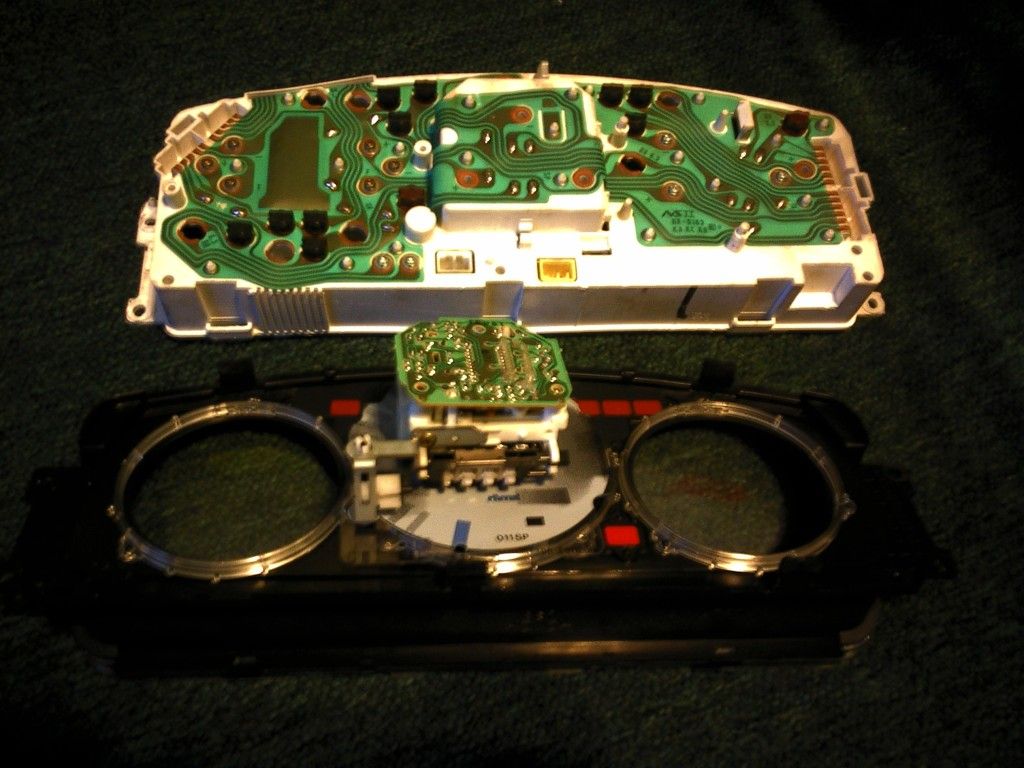
Unscrewed the speedometer gauge (look at the tutorial above to see which screws).
Popped off the Speedo PCB:

Then I proceeded to reflow some of the joints. To do this, I just touched the tip of the iron on the join and held it till the joint got liquidy. I also fed in some thin solder I had, you might not need to, I just did it cause I had it lying around.
You can see in the pics some of the ones I touched up. If you look at the speedo, you can see 4 pins in a row (2 and 2), I focused on the points where they pin into on the PCB.
I'm pretty sure it is these 4:
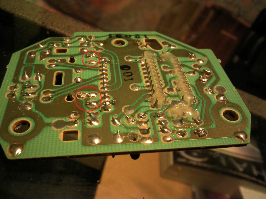
If you're pretty good with it, touch up anyones that you can. I did, so I'm not sure if touching just those 4 would fix it. Any ones that were reachable, I did. Didn't touch any that had glue around them.
Hope this helps someone.
Did the reflow fix.
Seemed to work so far. Figured I'd add in my pics.
I used this bernzomatic torch with the pen tip. A real soldering iron with a pointy tip would be better, but this is all I had.
Took apart the dash to get to the cluster.
Great writeup here:
http://www.superhonda.com/forum/f94/...-420kb-274853/
Separated the white and the black parts of the cluster:
Unscrewed the speedometer gauge (look at the tutorial above to see which screws).
Popped off the Speedo PCB:
Then I proceeded to reflow some of the joints. To do this, I just touched the tip of the iron on the join and held it till the joint got liquidy. I also fed in some thin solder I had, you might not need to, I just did it cause I had it lying around.
You can see in the pics some of the ones I touched up. If you look at the speedo, you can see 4 pins in a row (2 and 2), I focused on the points where they pin into on the PCB.
I'm pretty sure it is these 4:
If you're pretty good with it, touch up anyones that you can. I did, so I'm not sure if touching just those 4 would fix it. Any ones that were reachable, I did. Didn't touch any that had glue around them.
Hope this helps someone.
The following users liked this post:
05-15-2012, 09:20 AM
#19
Honda-Tech Member
Join Date: Nov 2011
Location: West Michigan
Posts: 159
Likes: 0
Received 0 Likes
on
0 Posts
Well in case this thread comes up in a search and the other ones I've posted my fix in don't, I'll copy it here too:
I took mine apart and tried to reflow the solder, but it lasted less than a week... first time I'd ever used a soldering iron though so I put it down to operator error. Next I tried baking the whole thing at 385 for 10 mins (preheated the oven, set the PCB on some rolls of foil propping it at the screw holes, on a cookie sheet...you can find instructions on baking computer video cards which is what I adapted)
worked flawlessly from october to february, in feb it started twitching and wigging out once in a while, by april it totally quit working in the cold again. (I guess it's not a morning person ) Probably will pop it out and try again, although now that it's not below 35 much at night it's working all day again so if it keeps working I may just put it off until I can buy a replacement board.
I suggest this cause it's a lot simpler than trying to reflow solder manually and not everybody has an iron. and at least for me, it worked a lot better. By the end of the 10 mins I could smell a little solder smell, but it dissipated pretty quickly. I wouldn't want to do it regularly without having a dedicated oven/toaster oven for it, but my personal risk assessment is that it isn't going to hurt anything once in a while.
08-16-2012, 01:06 PM
#20
Honda-Tech Member

Join Date: Sep 2011
Location: Charlotte, NC
Posts: 10
Likes: 0
Received 0 Likes
on
0 Posts
Just tried the resoldering the PCB and it solved all my problems too! Appreciate all the help guys. Just saved me $50 from having to buy another speedometer.
08-16-2012, 09:43 PM
#21
Trial User

Join Date: Aug 2012
Posts: 1
Likes: 0
Received 0 Likes
on
0 Posts
I I am so appreciative for this thread! I have been banging my head against the wall for months trying to figure out what was going on with my speedo. Especially because all the "experts" have different ideas of what it could be. I don't have the $$$ to just through darts at the board and hope.
By the way, I've got an '04 Civic VP. Problem started at maybe 115k miles, now at 122k.
What seems to be a little unique in my situation compared to most on this thread is that my speedo always moves, it's just sometimes it bottoms out at 25, 40, 60, or even 90! The other day I was going over 155 according to my speedo.
I did replace the VSS, no help. Ran the self-diagnostic last night a few times to make sure and it passed all phases every time. Also check and cleaned all connections.
I hope to be able to tackle the soldering this weekend, but it may have to wait a few weeks. I look forward to posting my results.
08-22-2012, 11:54 PM
#22
Honda-Tech Member

Join Date: Aug 2012
Posts: 8
Likes: 0
Received 0 Likes
on
0 Posts
Here is my question, now that I am considering changing out my cluster or some component for a fourth time. How hard would it be for someone to make a decent after market speedometer? Or at least a small round TV or view screen... something useful to fill the space? The fragility of these gauges is utter nonsense. I love Honda, but come on...
08-23-2012, 12:44 AM
#23
Trial User

Join Date: Aug 2012
Posts: 1
Likes: 0
Received 0 Likes
on
0 Posts
it also solved my problem with resoldering the pcb. thanks for this great thread.
Last edited by David23Kipp; 05-23-2013 at 02:29 PM.
 08-27-2012, 10:39 PM
#25
Honda-Tech Member
Join Date: Aug 2012
Posts: 8
Likes: 0
Received 0 Likes
on
0 Posts
Here is my question, now that I am considering changing out my cluster or some component for a fourth time. How hard would it be for someone to make a decent after market speedometer? Or at least a small round TV or view screen... something useful to fill the space? The fragility of these gauges is utter nonsense. I love Honda, but come on...
A few side notes, though. Honda charges $250 for a NEW speedo/trip/odo unit (does not include install) and Tacoma Speedometer (in WA) charges $180 for a same-day rebuild and $85 more to remove and install. The thread member offering $90 to rebuild now sounds quite reasonable, though my entire replacement used cluster on eBay was only $65 there is no guarantee everything will work (such as the odo). My advice now is to check everything before closing the dash and I will do this myself. Drive with the wires exposed, if needed. Should work fine. If not, keep digging. And I left the two screws above the stereo out so I don't have to dig into the center console next time. The fit seems quite snug even without them.