
5th Gen JDM Sidemarker Install Write Up
 05-26-2009, 11:58 AM
#1
Honda-Tech Member
Thread Starter
So for anyone that wanted to know how to go about putting on their 5th gen sidemarkers. Well here goes. I would like to thank my uncle for his help doing this and for writing the body cutting section up to make sure the right technique explanations were included!!
BODY CUTTING
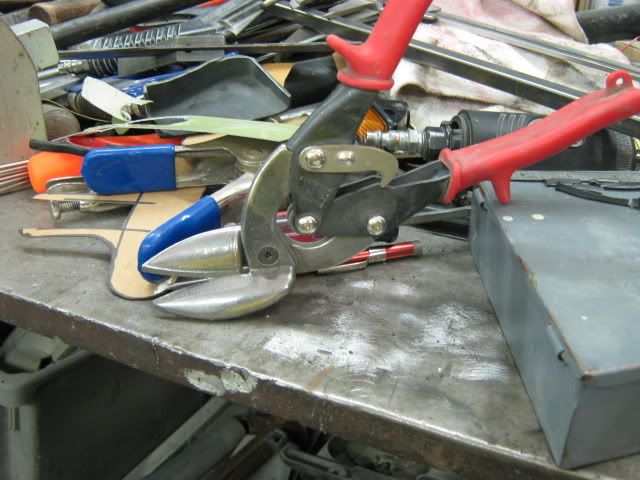
To start with, it�s hard to cover all possible scenarios of tool usage, not knowing what someone may have available. In the interest of keeping heat to a minimum, which tends to remove paint, this will be done with offset tin snips. Regular tin snips will cause a bit of distortion in the metal, offsets do a pretty good job of cutting with minimal distortion.
Offsets, left and right handed:
https://www.ductcleanersupply.com/sh...fset_snips.jpg
Regular aviation tin snips:
http://www.hg.com.au/images/productP...wis_3snips.jpg
Another method that can be used is cutoff wheels in pneumatic die grinders or the smaller version in a Dremel tool. In either of these cases, be sure to observe safety protection for the eyes, lest you not see your fine work when done, and be sure to work slowly, skip around with the cuts, and allow the metal to cool down between cuts. Don�t sit there too long where it will burn off your paint. A bit of touch up on the bare metal of the cut edge can be expected, but no sense in making more work.
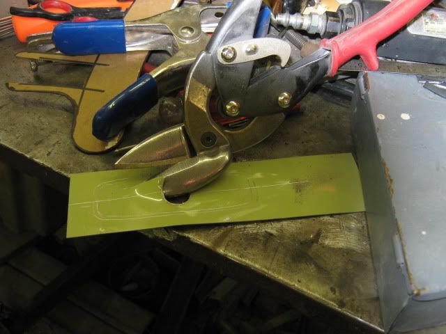
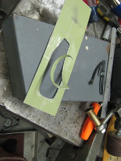
I find it easier to cut a template in cases like this. It gives you a chance to see if your proposed methods will work, if they need fine tuning, or perhaps other tools may make the job easier. In addition, a piece of scrap metal is much cheaper than another fender.
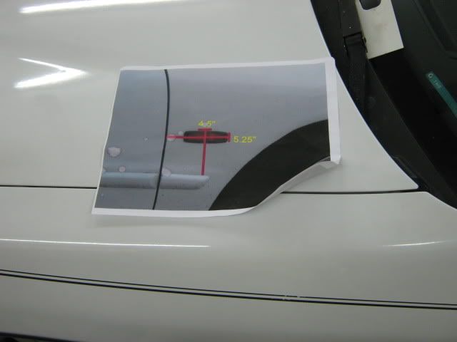
Even though the trusty dimensional guide found online was used, the dimensions used on the template reference the center mark of the hole, so some calculator action may be needed.
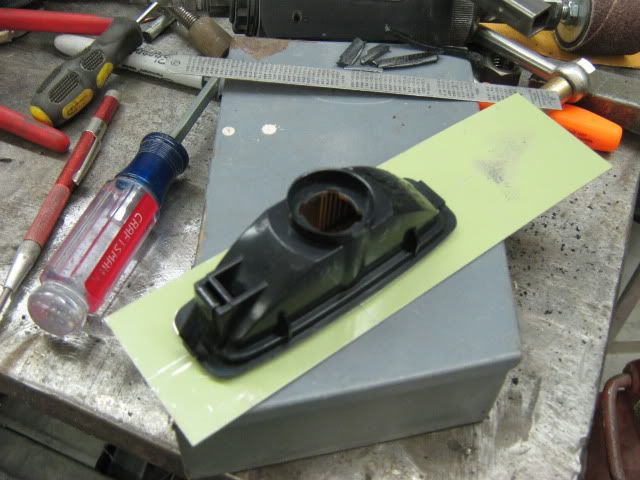
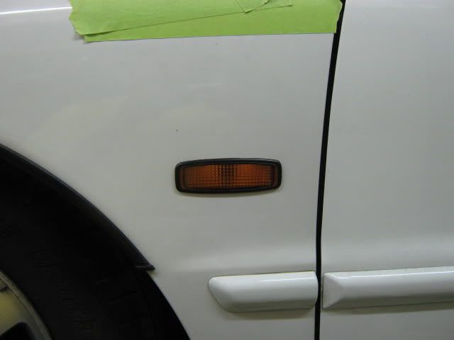
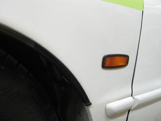
Measuring the marker light for required hole size:
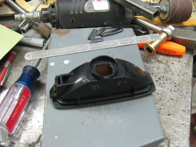
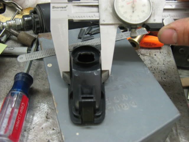
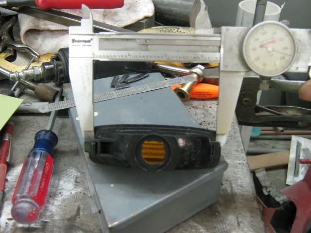
The light outline is scribed onto a scrap piece of painted steel, and centerline marks scribed as well:
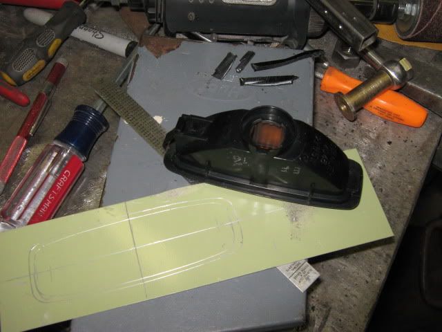
The measurements taken from the back side of the light are then divided by half, and then marked on either side of the center lines. Position the light so that two of the marks align, and scribe the proposed hole cut line on one quadrant of the template. Reposition and scribe for the other three quadrants. Now the template should show the hole cut line within the original outer scribe line.
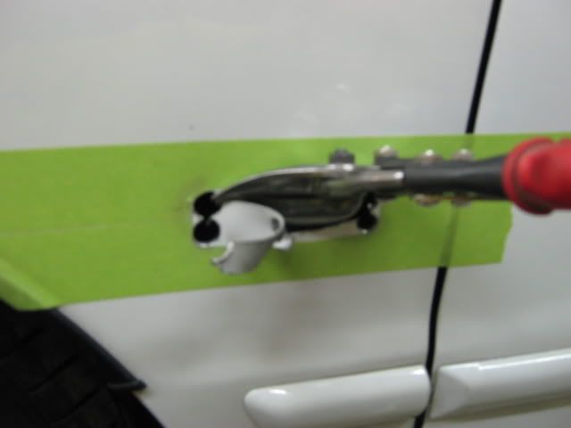
Drill a pilot hole and then enlarge to at least �� diameter to start the cut with the tin snips.
Start the cuts with the tin snips. If you�ve never used left and right hand tin snips before, you�ll soon realize where they are needed.
The red handled snips cut straight or around a left handed turn. The green handled snips cut straight or around a right handed turn.
One thing we soon discovered, although the offset snips do cut with minimal distortion, cutting around a sharp turn (the four corners) does introduce a bit of waviness to the panel. So when we get to the fenders, we�ll use a step drill in the four corners to make them as distortion free as possible.
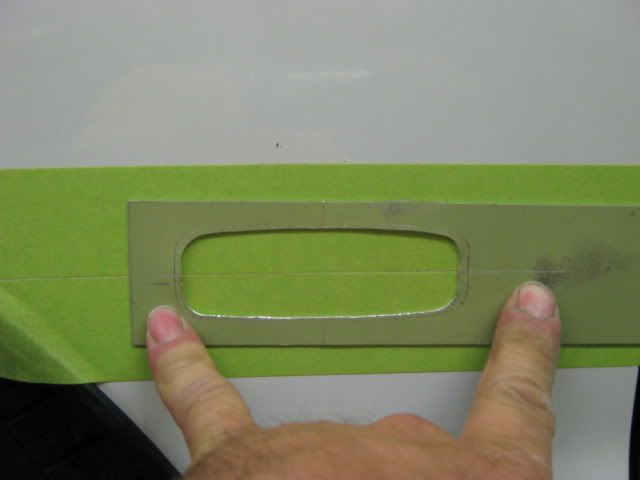
Here�s the light fitted to the template:
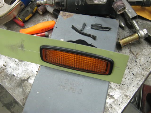
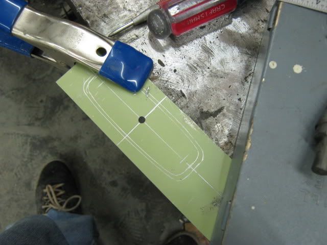
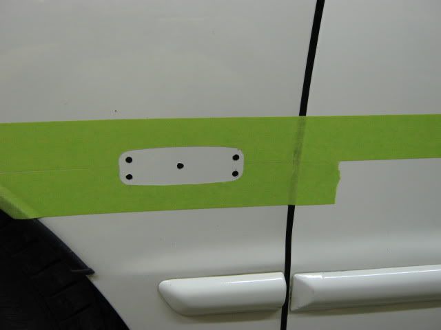
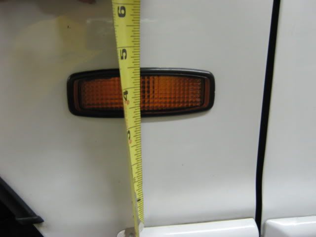
Now for cutting the fender, rather than marking the outer perimeter of the light, I chose to mark the centerlines for positioning the template. Using the measurements provided by the trusty online guide, half the distance of the height of the light is subtracted from the chart dimension to provide a horizontal reference. One measurement was taken from the trim on the fender, and another from farther back on the door, in hopes to have less chance of a crooked light. 1-1/2� painters tape used to mark these lines, as well as protect the paint during the hole cutting operation:
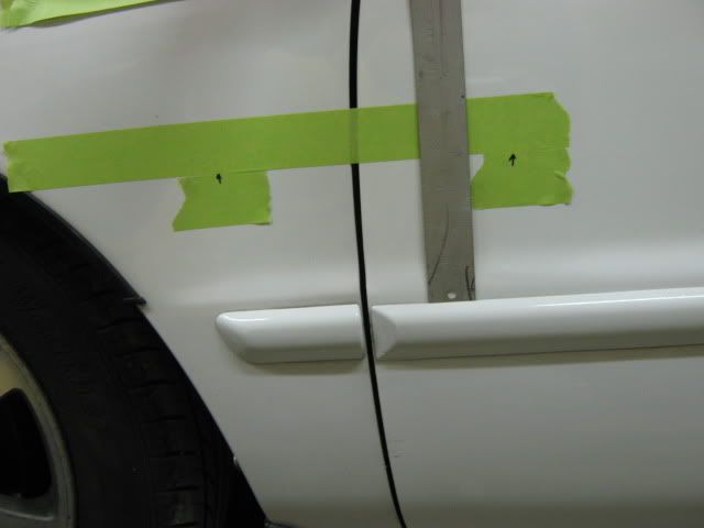
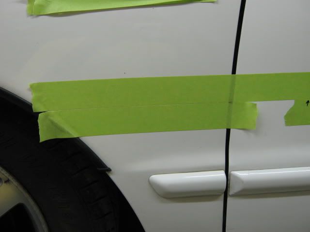
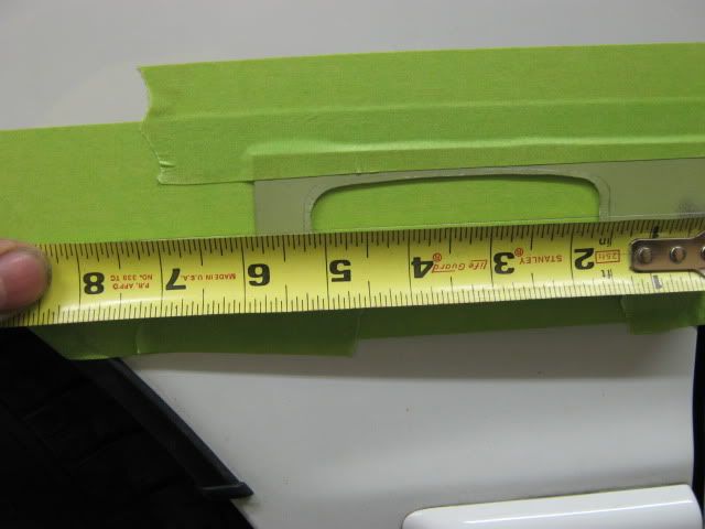
Template horizontal centerline is positioned directly on the joint of the two pieces of tape. The next measurement is taken from the rear edge of the fender to the outer scribe mark on the template, to position it correctly from front to back. Once in place, the rear edge of the template is trimmed to match the rear edge of the fender. This will speed up the process on the opposite fender.
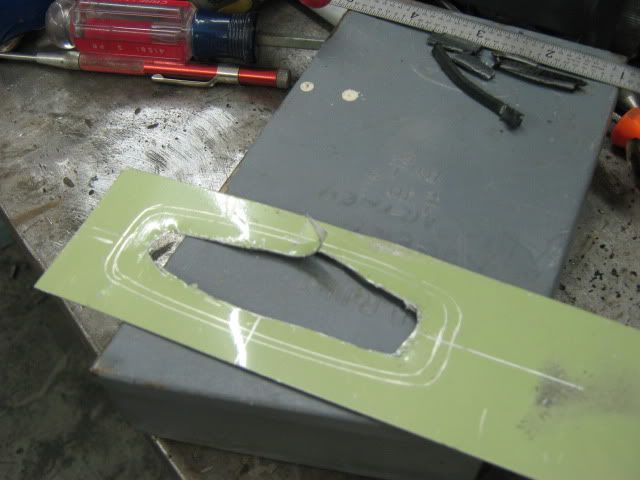
The template is taped down securely, and a sharp object used to cut out the hole location.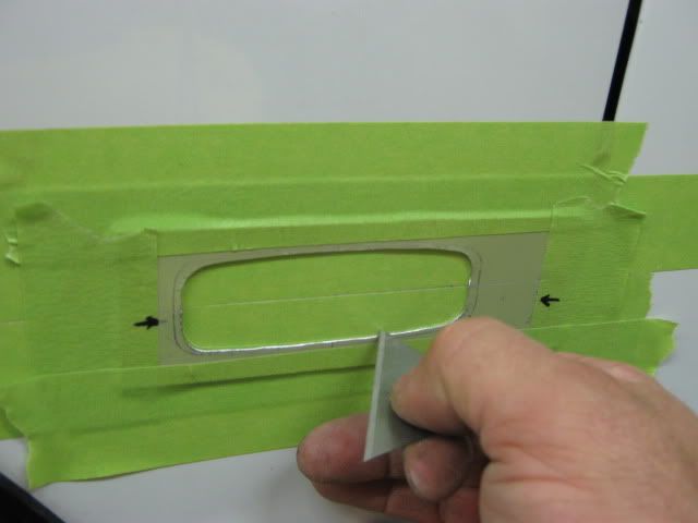
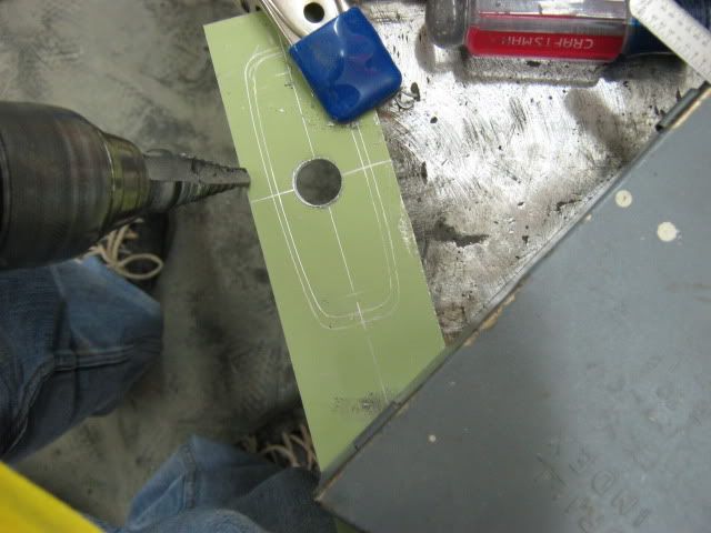
�� diameter holes are going to be used in the corners, so mark holes centers in �� in from the sides.

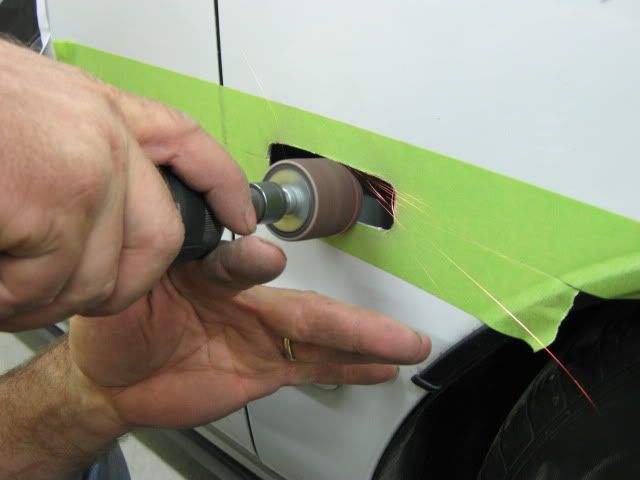
Pilot drill the holes, then enlarge to �� diameter using a sharp step drill. Don�t push too hard, the sheet metal will deform. Let the cutter do the cutting. If your center mark was slightly off, i.e. too close to the corners, stop drilling when you reach the edge of the tape. You can clean it up later with a drum sander on the Dremel.
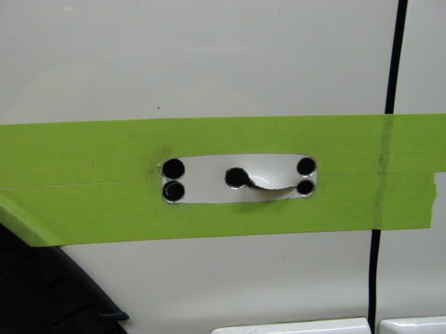
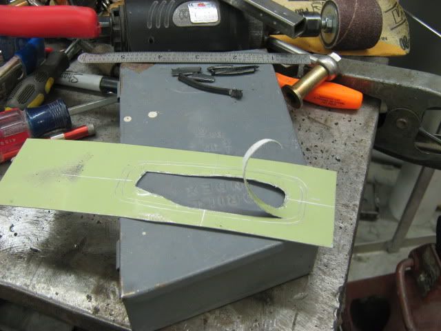
Here�s where the left and right hand snips come in real handy.
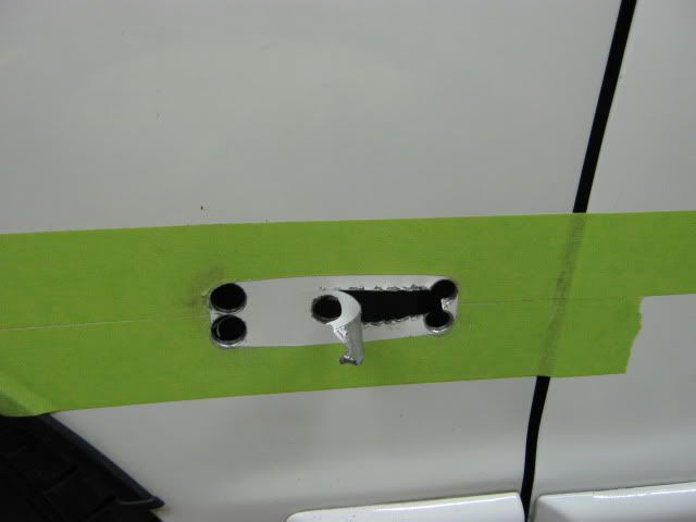
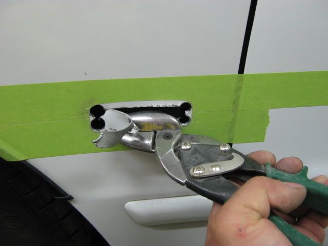
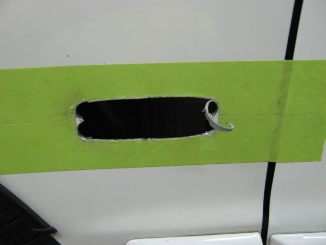
Edges may require some �fine tuning� with a drum sander. We used both the Dremel for the sides and corners, and this larger version for the top and bottom edges.
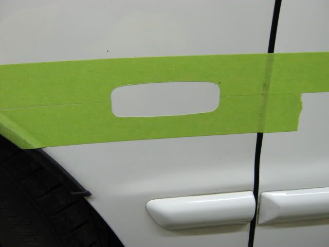
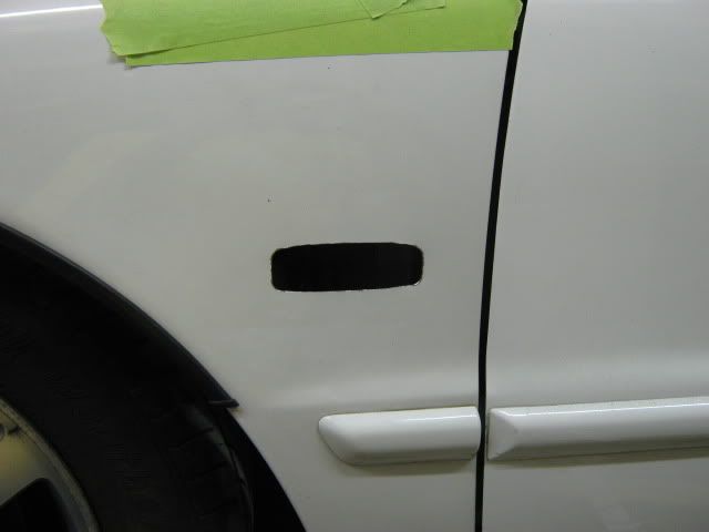
The finished hole. Some touch up paint on the bare metal exposed is advisable, but as Chris is supposed to repaint in the near future, we skipped that step.

WIRING
Ok now for my part, the wiring. Well first it depends on the headlight housing. If you have the stock USDM headlight housing or aftermarket headlight then you will need to splice off on of the harnesses. Now the wires you want are the blinker ones. It should be a brown plug going in on the corner lens and if you turn the blinker to the corresponding headlight on, that is the one. Now it is all up to you how you want to do this. You can cut the brown plug off and solder a new set of two wires in or if you cannot solder or do not want to, a butt connector and shrink wrap can work. From there just make sure you have enough wire to get to the fender and then solder or butt connect it back into the car's blinker wiring harness.
Now if you have JDM black housing headlights or DEPO black housing headlights you already know there is not a blinker bulb in the corner lamp already, hence why JDM accords have a side marker but not blinker in the corner lamp and the exact opposite for the USDM. From there it is the same as the above when it comes to just soldering in another set of positive and negative wires.
You can also buy the PasswordJDM sidemarker harness set which includes the brown harness plugs and enough wire to get the job done.
Hope this helps and good luck to anyone taking this project on.
BODY CUTTING
To start with, it�s hard to cover all possible scenarios of tool usage, not knowing what someone may have available. In the interest of keeping heat to a minimum, which tends to remove paint, this will be done with offset tin snips. Regular tin snips will cause a bit of distortion in the metal, offsets do a pretty good job of cutting with minimal distortion.
Offsets, left and right handed:
https://www.ductcleanersupply.com/sh...fset_snips.jpg
Regular aviation tin snips:
http://www.hg.com.au/images/productP...wis_3snips.jpg
Another method that can be used is cutoff wheels in pneumatic die grinders or the smaller version in a Dremel tool. In either of these cases, be sure to observe safety protection for the eyes, lest you not see your fine work when done, and be sure to work slowly, skip around with the cuts, and allow the metal to cool down between cuts. Don�t sit there too long where it will burn off your paint. A bit of touch up on the bare metal of the cut edge can be expected, but no sense in making more work.
I find it easier to cut a template in cases like this. It gives you a chance to see if your proposed methods will work, if they need fine tuning, or perhaps other tools may make the job easier. In addition, a piece of scrap metal is much cheaper than another fender.
Even though the trusty dimensional guide found online was used, the dimensions used on the template reference the center mark of the hole, so some calculator action may be needed.
Measuring the marker light for required hole size:
The light outline is scribed onto a scrap piece of painted steel, and centerline marks scribed as well:
The measurements taken from the back side of the light are then divided by half, and then marked on either side of the center lines. Position the light so that two of the marks align, and scribe the proposed hole cut line on one quadrant of the template. Reposition and scribe for the other three quadrants. Now the template should show the hole cut line within the original outer scribe line.
Drill a pilot hole and then enlarge to at least �� diameter to start the cut with the tin snips.
Start the cuts with the tin snips. If you�ve never used left and right hand tin snips before, you�ll soon realize where they are needed.
The red handled snips cut straight or around a left handed turn. The green handled snips cut straight or around a right handed turn.
One thing we soon discovered, although the offset snips do cut with minimal distortion, cutting around a sharp turn (the four corners) does introduce a bit of waviness to the panel. So when we get to the fenders, we�ll use a step drill in the four corners to make them as distortion free as possible.
Here�s the light fitted to the template:
Now for cutting the fender, rather than marking the outer perimeter of the light, I chose to mark the centerlines for positioning the template. Using the measurements provided by the trusty online guide, half the distance of the height of the light is subtracted from the chart dimension to provide a horizontal reference. One measurement was taken from the trim on the fender, and another from farther back on the door, in hopes to have less chance of a crooked light. 1-1/2� painters tape used to mark these lines, as well as protect the paint during the hole cutting operation:
Template horizontal centerline is positioned directly on the joint of the two pieces of tape. The next measurement is taken from the rear edge of the fender to the outer scribe mark on the template, to position it correctly from front to back. Once in place, the rear edge of the template is trimmed to match the rear edge of the fender. This will speed up the process on the opposite fender.
The template is taped down securely, and a sharp object used to cut out the hole location.
�� diameter holes are going to be used in the corners, so mark holes centers in �� in from the sides.
Pilot drill the holes, then enlarge to �� diameter using a sharp step drill. Don�t push too hard, the sheet metal will deform. Let the cutter do the cutting. If your center mark was slightly off, i.e. too close to the corners, stop drilling when you reach the edge of the tape. You can clean it up later with a drum sander on the Dremel.
Here�s where the left and right hand snips come in real handy.
Edges may require some �fine tuning� with a drum sander. We used both the Dremel for the sides and corners, and this larger version for the top and bottom edges.
The finished hole. Some touch up paint on the bare metal exposed is advisable, but as Chris is supposed to repaint in the near future, we skipped that step.
WIRING
Ok now for my part, the wiring. Well first it depends on the headlight housing. If you have the stock USDM headlight housing or aftermarket headlight then you will need to splice off on of the harnesses. Now the wires you want are the blinker ones. It should be a brown plug going in on the corner lens and if you turn the blinker to the corresponding headlight on, that is the one. Now it is all up to you how you want to do this. You can cut the brown plug off and solder a new set of two wires in or if you cannot solder or do not want to, a butt connector and shrink wrap can work. From there just make sure you have enough wire to get to the fender and then solder or butt connect it back into the car's blinker wiring harness.
Now if you have JDM black housing headlights or DEPO black housing headlights you already know there is not a blinker bulb in the corner lamp already, hence why JDM accords have a side marker but not blinker in the corner lamp and the exact opposite for the USDM. From there it is the same as the above when it comes to just soldering in another set of positive and negative wires.
You can also buy the PasswordJDM sidemarker harness set which includes the brown harness plugs and enough wire to get the job done.
Hope this helps and good luck to anyone taking this project on.
 05-26-2009, 02:30 PM
#3
Honda-Tech Member
Thread Starter
wow thanks man!! Glad it all made sense and everything because there is a lot of information there,
05-26-2009, 03:11 PM
#5
Honda-Tech Member
Thread Starter
bahahaha. talk to my uncle about that one. he is the word for perfection. I get a lot of it from him now when I work at the shop. you should see the new lip, it looks perfect too haha.
05-26-2009, 03:31 PM
#6
Honda-Tech Member
Join Date: Aug 2005
Location: Pompano Beach, FL, USA
Posts: 3,495
Likes: 0
Received 5 Likes
on
4 Posts
hummm, nice... i think after seeing this and knowing that your uncle did it, the lip must be looking very good. Post the pictures man... let's see how it's looking already!

Trending Topics
05-26-2009, 04:26 PM
#8
Honda-Tech Member
Thread Starter
Well it will be painted this week, I can put some mock up pictures on the squad forum if you want? Just the lip on my car after I wet sanded the high build primer.
05-26-2009, 11:37 PM
#9
Honda-Tech Member
Join Date: Apr 2004
Location: Buckeye Country, United States
Posts: 397
Likes: 0
Received 0 Likes
on
0 Posts
Very nice writeup. You could always send that template my way as I'm going to install mine this weekend.
05-27-2009, 02:16 PM
#13
Honda-Tech Member
Thread Starter
05-27-2009, 02:18 PM
#14
Honda-Tech Member
Thread Starter
Yeah whatever works to make sure you cover up the bare metal. as stated i did not do mine as I am going to be repainting it soon, but if the paint job gets postponed I will take them off one day and just touch the edges up with something,
05-27-2009, 04:12 PM
#18
Honda-Tech Member
Thread Starter
06-02-2009, 01:14 PM
#21
Honda-Tech Member
Thread Starter
Thanks man! Lots of credit to my uncle for all the help!! Just hope it helps somebody and gives them some direction on how to do this properly for a professional looking install.
06-06-2009, 07:49 PM
#22
New User
Join Date: Jun 2009
Posts: 5
Likes: 0
Received 0 Likes
on
0 Posts
Hey, let's cut some more holes!
Hindsight 20/20 and all that good stuff, I think if someone were to make a template in a similar fashion, it would be nice to have the offset of the hole (distance up from the trim) preset/precut onto the template. Then drop the template in place on top of the fender trim, measure the distance from the back edge of the fender, and mark your hole.
No fuss no muss. You'll have to excuse me, I don't normally think of everything the first time out. (those are my paws holding the tin snips)
Last edited by MP&C; 06-06-2009 at 08:01 PM.
06-09-2009, 05:04 PM
#23
Honda-Tech Member
Thread Starter
Haha. Either that or start mailing our template around to all the 5th gens that want it. Get it back with everyones name on it or something that has had it or whatever.
 06-10-2009, 11:11 AM
#25
Honda-Tech Member
Thread Starter
I think that would be too low personally, but then again never seen it done. Do what you like and see how it turns out.