When you click on links to various merchants on this site and make a purchase, this can result in this site earning a commission. Affiliate programs and affiliations include, but are not limited to, the eBay Partner Network.
D16Y7 Photos of Plastiguage results for Crankshaft Main Bearing Clearances. Any good?
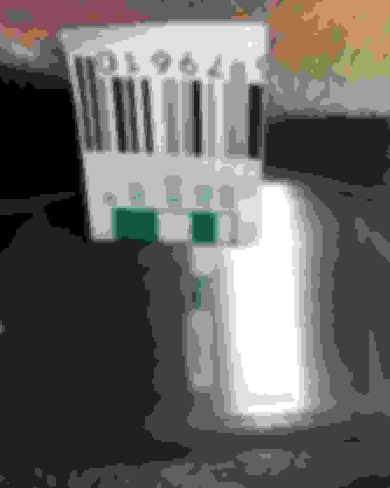
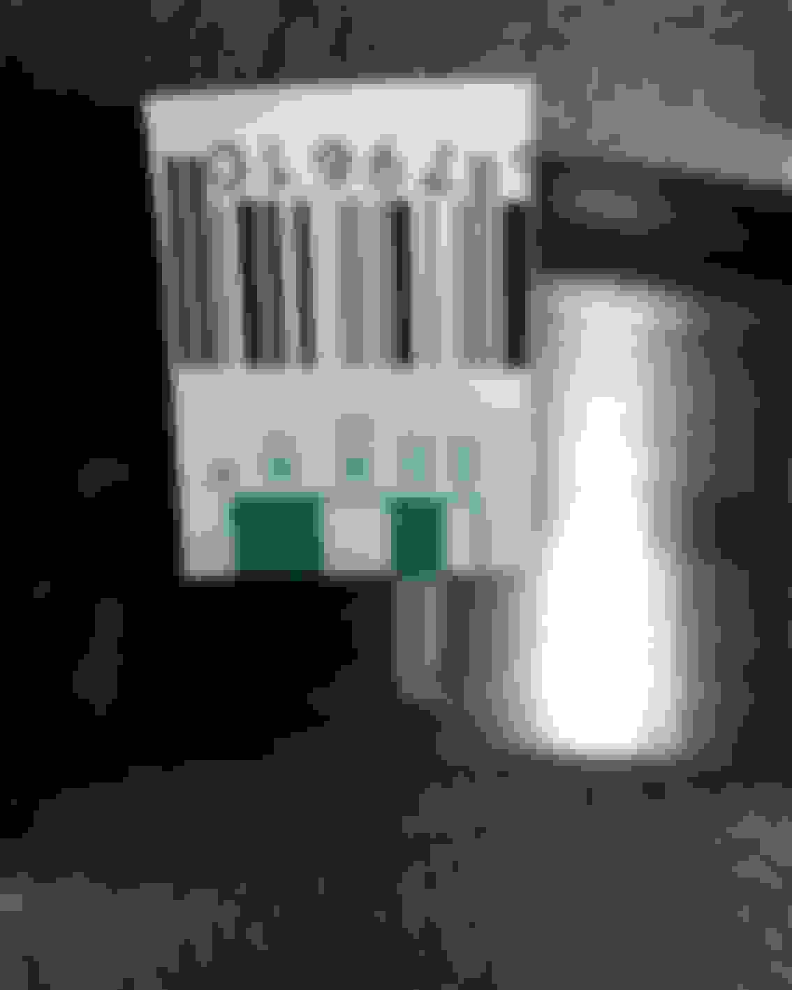
Ok, so the factory service manual states that 0.02" is the service limit for the main bearings on the D16Y7 and my plastiguage results are right there and I'd like some advice on whether or not this will be ok.
This is just a stock D16Y7 build, it's the first engine I've ever rebuilt and I'm trying to get everything right. I've done my homework, but there are times when no amount of research can take the place of experience. This feels like one of those situations. I'm not too sure about how precise plastiguage is, or how important it is to get the clearances a little tighter here, but I'm hoping this will work.
I used STD King bearings and had no machine work done to the crank journals since my machinist said it looked great. I lightly polished them with 600 grit wet and dry and a shoe lace, but I was fearful of overdoing it and doubt it removed any material. The journals were mic'd and the measurements are well within STD spec varying from 54.974 - 54.981mm.
So, how do these readings look? Some input from those with experience would be great.
Re: D16Y7 Photos of Plastiguage results for Crankshaft Main Bearing Clearances. Any g
After looking back through my photos, I'm feeling like I should pick up slightly thicker bearings for the #1 and #5 mains. Advice on this will be much appreciated.
Re: D16Y7 Photos of Plastiguage results for Crankshaft Main Bearing Clearances. Any g
Thank you for sharing, but I'm hoping for confidence building replies soon. I'm already a little nervous about this build. I didn't have any spun bearing, but I did have a bad water pump that drained the coolant, leading to an overheat and blown head gasket. The head was also warped. The block was within spec in every way, but I went and had a machinist resurface it. I honed it myself with one of those flex-hone ball brushes in a drill and it worked great. I highly recommend it. I think I used the 360 grit silicon dioxide, but I can't remember. I spun it at 750 RPMs, checked with a digital tach I bought on eBay and went down and up with in about 12 times in each cylinder. I bought a rebuilt head that I inspected based on the FSM and it checks out. I also had the crank, pistons, old rings and bearings checked out by the machinist who took care of my block. He advised to get new rings and bearings, so I did that and I think I am ready to assemble.
I am just a little concerned about the clearances on my mains being a little loose. If I don't get more input by tomorrow, I'm gonna just go for it. As I've read, "loose is fast", and I seem to be within the service limit, so I think it's fine. I thought I would get more replies on this.
Re: D16Y7 Photos of Plastiguage results for Crankshaft Main Bearing Clearances. Any g
I think you will be okay with that clearance, did you use a feeler guage to check side to side on the rods? if thats in spec you will most likely be just fine, most aftermarket stuff runs bigger clearances too by the way.. i kno this is all stock but i wouldnt be worried, oversized would be too tight
Re: D16Y7 Photos of Plastiguage results for Crankshaft Main Bearing Clearances. Any g
Thank you for the input. The side clearance on the rods is right around 0.3mm, so I think I'm good to begin assembly today! Finally!! This turned out to be more work than I thought it would be. It was supposed to be a simple water pump and head gasket replacement, but one thing lead to another and six weeks later, here I am.
Re: D16Y7 Photos of Plastiguage results for Crankshaft Main Bearing Clearances. Any g
Plasiguage results look good to me.
I've always been weary of DIY hone jobs. There's so much science into it that I feel if you don't have precision equipment, you may not get exactly the right crosshatch and ring seating.
Things like speed, grit, stroke, crosshatch angle, and finish all play a factor in getting the rings to seat correctly. Even the pressure of the stones against the cylinder. Doing it by hand can be inconsistent. I do wish you the best of luck however.
Re: D16Y7 Photos of Plastiguage results for Crankshaft Main Bearing Clearances. Any g
Thank you for the input. In my research, I have come to appreciate the art and science that goes into engine building. This car is my wife's commuter, so I do want it to turn out well, however this is more of a learning experience than anything else. If it runs great, all the better. Since I am here to learn, all input and advice is greatly appreciated.
I tried to account for as many of the variables as possible in the honing/deglazing process. Also, it was more of a deglazing that a honing. I could still see crosshatching in the cylinders when I used a bright light. With the ball hone, or Flex Hone brush, the pressure is supposedly accounted for by the slightly oversized brush and flex strength of the stiff nylon that holds the 320 grit silicon carbide cutting beads. The ideal rotational speed is said to be around 700 rpms with one up and down per second. If all of this was accurate, the only part where inaccuracy could have entered this formula was how fast I went up and down. I tried to keep it to one round a second as it was suggested to me and I measured the RPMs with a digital tach I used to use for the electric RC plane motors I used to build. From the looks of it, I think the deglazing turned out pretty well. No way of knowing until I get it running though.
I also wanted to state something about the topic that was mentioned to me in another thread. There is NO SUBSTITUTION for proper measuring of the crank shaft main and rod journals, bearings and oil clearances thereof. Plastigauge should only be used as one last check to make sure you have the bearings in the right place and such, after they have all been properly measured. I had my crank measured in every which way by professional to make sure it was still good and useable and then I selected the bearings based on his recommendation. It seems like it turned out well.
The other day, I used one of those clamp type ring compressors to fit my pistons in the cylinders, but I didn't like the way it rotated as it tightened down around the piston. I was worried that it may have moved the rings, so i pulled one out today and sure enough, the rings on the one piston had move a good 10 degrees and was too close to the wrist pin in my opinion. SO... I decided to order one of the tapered ring compressors and hopefully it will arrive soon so I can redo the piston rings and continue this build.
It sure felt good to finally see the cleaned up pistons back in there... but then that bad feeling I had about the rings moving got the better of me.
If there is anything that anyone can think of that I might have overlooked, please let me know.
Re: D16Y7 Photos of Plastiguage results for Crankshaft Main Bearing Clearances. Any g
Looks good man. Sounds like you've done your homework! Patience and precision are key!
Do you have a break in method in mind? Myself and many others have had good results using Motomans instructions. Basically put some load on the engine to push the rings against the cylinders as quickly as possible once it's warmed up. The first several minutes are the oopportune time to get the rings seated.
Re: D16Y7 Photos of Plastiguage results for Crankshaft Main Bearing Clearances. Any g
Thank you again for stopping in here and sharing advice, I was very unsure about this whole process at first, but doing the homework helped me feel like it will turn out alight. I'm starting to feel good about it now though. I'm looking forward to the tapered ring compressor to get here so I can get moving on this build again soon.
I'm liking Motoman's though process. I remember reading this when I first started researching engine building, thank you for bringing me back to it! I like what he has to say about newer engines with a finer honing pattern requiring new methods when compared to the older rough honed engines. One thing I need to also do is remeasure the piston ring back-gap when I pull them back out. I measured the back-gap on the top ring of one piston and assumed it would be good for all of them. I just wanted to start building so bad that I started to rush things. Haste make waste. So, I will make sure all is well this time before I put them back in. I didn't realize how important the back gap is. It's ridiculous how much there is to know...

 09-05-2016, 09:53 PM