
Porting for Duh-mestic V8's, Just for Mr. Rocket
 08-31-2013, 05:53 PM
#1
Honda-Tech Member
Thread Starter
Join Date: Feb 2003
Location: Houston, TX
Posts: 1,171
Likes: 0
Received 0 Likes
on
0 Posts
SECTION I - Intro
There has been an interest in my genitals from the Honda-Tech community recently. From the way it swings to the size and dimensions, Mr. Rocket has made several off topic comments in some of the more technical threads in regards to said genitals. I know what you�re thinking. This is not how I had ever imagined starting a technical write up either, but well, here we are.
In an effort to steer the discussion back towards technical topics, to put in place a technical cylinder head porting thread where another was promised and is as of yet undelivered, and to satisfy Mr. Rocket�s curiosity as to the size of my genitals, I am giving you guys a peak into what V8 domestic guys are really looking at these days as far as modifying cylinder heads in the pursuit of power. While it may or may not apply to your mad tyte JDM engine, it may spark new ideas and ways of thinking, or at least show that us duh-mestic guys are way past the days of � race cams and double pumper carburetors.
The engine platform in question here will be the Gen III and Gen IV small block Chevy V8, also known as the LS series. These engines are plentiful, relatively inexpensive, and can produce phenomenal power output with very little effort or expense. One element of design that made the Gen III engines unique is the small and efficient �cathedral port� cylinder heads, named so because of the tall and skinny shape of the intake ports. Stock intake valve sizes ranged from 1.89� (48mm) to 2.00� (50.8mm) with port volumes roughly 200-210cc depending on the casting.
The so called �evolution� of the Gen III family is the Gen IV family of LS engines. By contrast, the ports in the Gen IV cylinder heads grew considerably larger and utilized much larger valve sizes. The ports grew to roughly 260-270cc and utilized either 2.160� (54.9mm) or 2.200� (55.9mm) intake valves, and featured a �rectangle port� shape typical of traditional V8 intake ports.
SECTION II - Hypothesis
There is a pretty large gap between the operating range of a race oriented and street oriented V8 OHV engine. Street engines featuring mass produced hydraulic roller lifters will typically turn a maximum of 7000-7500RPM, while the race engines featuring aftermarket solid roller lifters will see upwards of 9500+RPM. This difference changes the approach one should take when porting cylinder heads to perform their best in a target RPM range. One of the key similarities, though, is that bigger intake valves are king, but for different reasons.
Since RPM can be thought of as a horsepower multiplier, race engines use bigger intake valves and bigger ports to move the power band higher and higher. Teams are constantly trying to find ways to refine their valve train so that they can sustain more RPM. Bigger intake valves and larger cross sectional areas in the ports allow the heads to meet the airflow demands of the engines operating at these higher engine speeds. There is a lot more to it, obviously, but this isn�t about a race engine, so we�ll keep it brief and leave it at that.
For a street engine, you want the big intake valves as well, but not the big ports. The port should not grow as big as a race engine port because the operating range is lower and the port needs to be sized accordingly. The cross sectional areas in the ports will have a large influence on how fast the air moves through the port and how high the torque will peak in the operating range of the engine. Too large, and the airspeed will be too slow and the VE will suffer, typically resulting in a �peaky� power band with good peak power but poor overall power. Too small, and it will peak too soon and cause the power to fall off too soon as well. There are formulas out there that calculate where torque will peak based on cross sections, but I won�t get to that until later.
In the Gen III/IV engine family, you don�t really get an ideal street engine induction system. You can have the small ports and small valves of the Gen III or the big valve and big ports of the Gen IV. What you want is a combination of the two to get it right. In the following pages, I will be machining a Gen III cylinder head with its small ports to accept the large valve from a Gen IV cylinder head, and port the head to manipulate the flow curve, all while documenting the flow numbers along the way. At the end of the test, this set of cylinder heads will be validated with dyno numbers to be the final say so as to the success or failure of the experiment, regardless of what the Flowbench says.
SECTION III � Baseline
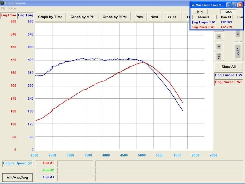
Obviously, to know if the heads are better, we need a baseline with which to measure the gain or loss. The test vehicle is my 2000 Pontiac Trans Am. The original 5.7L LS1 was swapped out for a 6.2L shortblock that I built about a year ago. The heads from the LS1 were reused, but now have aftermarket 2.02� intake and 1.60� exhaust valves and minor bowl work, resulting ion a 209cc port volume. The cam is a Comp Cams hydraulic roller grind with 235� duration and .598� net lift on the intake and exhaust, 111� LSA, and installed with a 109� intake centerline. On the dyno, the engine made over 430ft-lbs of torque and 400whp before the clutch would slip at 5000RPM. Compared to other 6.2L engines with the Gen IV �rectangle port� heads and an aftermarket camshaft, my engine is making 30-50 more ft-lbs at 3000RPM, proving that there really is something to the smaller, more efficient ports of the Gen III engines.
Before the new heads are installed, the new clutch will be installed and the car will be dyno�d again for baseline numbers. This section will be updated at a later date for a valid baseline.
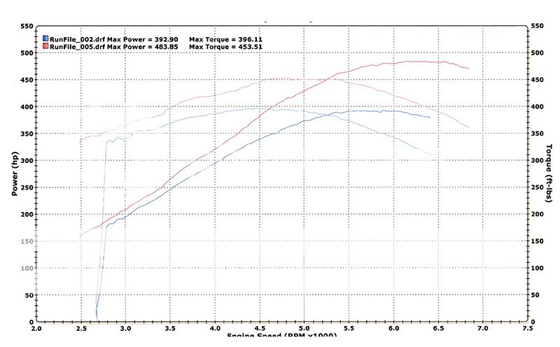
Pictured below; top graph is my 6.2L Trans Am on a Mustang Dyno and below that is a 6.2L Corvette with "rectangle port" heads, cam, headers, and exhaust on a Dynojet Dyno.
SECTION IV � The Preliminary
In the hierarchy of the Gen III heads, the 243/799 castings are on top. Compared to the other heads, the 243/799 ports have a taller and wider short turn radius keep the air from shearing off at higher airspeeds and result in much higher flow and power numbers. These heads have made as much as 850hp in naturally aspirated race engines, so they are proven performers. Before machining on the 243 heads that will be used in final testing, a preliminary trial will be done to a less desirable 862 casting. These heads came on most of the smaller 4.8L/5.3L truck engines and are only even remotely desirable because they feature the smallest combustion chambers of any Gen III/IV cylinder head.
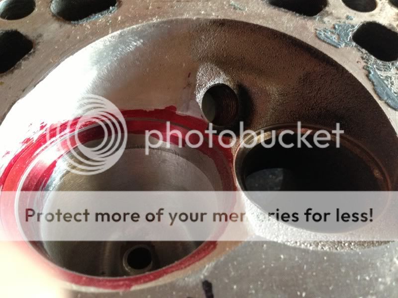
The stock seat inserts are powdered metal alloy and are only 2.02� in diameter. In order to use a valve larger than 2.02�, you must remove the old insert and install larger inserts. For this, the 862 head is loaded onto the Sunnen VGS-20 seat and guide machine. The seat insert is machined out, and then another pass cuts the counterbore to size. The head is then taken off the VGS-20 to press in the new seats.
Pictured below is the chamber with the intake seat machined out to accommodate the new Melling 2.170� diameter seat insert.

The new seat inserts are left in the freezer overnight to let them shrink, or contract. This makes pressing the seat insert into the head easier and less likely to scrape the aluminum bore and trap material under the seat. Once the seats have been pressed in, the head goes back into the VGS-20 for the valve job. For the valve job, a special cutter is used that has a 3 angle profile built into it. The top, seat, and bottom angles and widths are machined in all at the same time. Additional angles are cut into the port to rough in the throat and create a less abrupt transition from the throat to the chamber. The first and last valve job is lapped in with a fine grit compound to check the seat concentricity.
After the valvejob is cut, the cylinder head is taken off the VGS-20 and setup on the porting bench. At this point, only a basic cleanup is done before the first flow test. The throat diameter is set to 1.80" as a starting point, the guide boss is narrowed only conservatively, and the transitions from the valve job into the chamber and into the throat are blended in. The Gen III cylinder heads also have a rocker boss that protrudes into the port. This obstruction is also removed, as well as all casting flash.
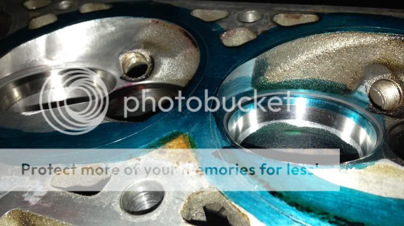
Pictured below is the first chamber with the valve job cut for the larger 2.160� valve. You can see in the port that it has been cleaned up and polished. The red dye is part of the lapping process and helps make any imperfections in the seat sealing surface more visible. Also, notice how only the intake side of the chamber has been worked on.
The heads then make their way onto the Superflow SF600 Flowbench. While the basic models will require the operator to take the percentage readings from the manometer and calculate the flow numbers, this model is equipped with the Flowcom option, which does the calculations for you, among other features. The 862 casting was tested with a 2.00� intake valve cut in one chamber and the 2.160� valve in another. Additionally, an 821 casting LS3 �rectangle port� head was tested that had been CNC ported and used a more aggressive 50� valve job. The following data was collected with a 4.00� bore test plate at 28� of H2O.
862 Casting w/ 2.00� Intake Valve
Lift Intake
0.050 36
0.100 72
0.200 133
0.300 187
0.400 227
0.500 237
0.600 236
0.650 240
862 Casting w/ 2.160� Intake Valve
Lift Intake
0.050 36
0.100 69
0.200 137
0.300 206
0.400 254
0.500 271
0.550 269
0.600 273
0.650 278
0.700 281
821 Casting w/ 2.160� Intake Valve CNC ported & 50� VJ
Lift Intake
0.050 33
0.100 67
0.200 138
0.300 214
0.400 278
0.500 326
0.550 336
0.600 345
0.650 349
0.700 344
Stay tuned. The next update I will begin the machining on the 243 heads, plus further modification of the 862 port to see if the low and mid lift numbers can't be improved.
Plus, we'll see if Rocket has been able to produce any kind of write up like he promised almost two months ago...lol
There has been an interest in my genitals from the Honda-Tech community recently. From the way it swings to the size and dimensions, Mr. Rocket has made several off topic comments in some of the more technical threads in regards to said genitals. I know what you�re thinking. This is not how I had ever imagined starting a technical write up either, but well, here we are.
In an effort to steer the discussion back towards technical topics, to put in place a technical cylinder head porting thread where another was promised and is as of yet undelivered, and to satisfy Mr. Rocket�s curiosity as to the size of my genitals, I am giving you guys a peak into what V8 domestic guys are really looking at these days as far as modifying cylinder heads in the pursuit of power. While it may or may not apply to your mad tyte JDM engine, it may spark new ideas and ways of thinking, or at least show that us duh-mestic guys are way past the days of � race cams and double pumper carburetors.
The engine platform in question here will be the Gen III and Gen IV small block Chevy V8, also known as the LS series. These engines are plentiful, relatively inexpensive, and can produce phenomenal power output with very little effort or expense. One element of design that made the Gen III engines unique is the small and efficient �cathedral port� cylinder heads, named so because of the tall and skinny shape of the intake ports. Stock intake valve sizes ranged from 1.89� (48mm) to 2.00� (50.8mm) with port volumes roughly 200-210cc depending on the casting.
The so called �evolution� of the Gen III family is the Gen IV family of LS engines. By contrast, the ports in the Gen IV cylinder heads grew considerably larger and utilized much larger valve sizes. The ports grew to roughly 260-270cc and utilized either 2.160� (54.9mm) or 2.200� (55.9mm) intake valves, and featured a �rectangle port� shape typical of traditional V8 intake ports.
SECTION II - Hypothesis
There is a pretty large gap between the operating range of a race oriented and street oriented V8 OHV engine. Street engines featuring mass produced hydraulic roller lifters will typically turn a maximum of 7000-7500RPM, while the race engines featuring aftermarket solid roller lifters will see upwards of 9500+RPM. This difference changes the approach one should take when porting cylinder heads to perform their best in a target RPM range. One of the key similarities, though, is that bigger intake valves are king, but for different reasons.
Since RPM can be thought of as a horsepower multiplier, race engines use bigger intake valves and bigger ports to move the power band higher and higher. Teams are constantly trying to find ways to refine their valve train so that they can sustain more RPM. Bigger intake valves and larger cross sectional areas in the ports allow the heads to meet the airflow demands of the engines operating at these higher engine speeds. There is a lot more to it, obviously, but this isn�t about a race engine, so we�ll keep it brief and leave it at that.
For a street engine, you want the big intake valves as well, but not the big ports. The port should not grow as big as a race engine port because the operating range is lower and the port needs to be sized accordingly. The cross sectional areas in the ports will have a large influence on how fast the air moves through the port and how high the torque will peak in the operating range of the engine. Too large, and the airspeed will be too slow and the VE will suffer, typically resulting in a �peaky� power band with good peak power but poor overall power. Too small, and it will peak too soon and cause the power to fall off too soon as well. There are formulas out there that calculate where torque will peak based on cross sections, but I won�t get to that until later.
In the Gen III/IV engine family, you don�t really get an ideal street engine induction system. You can have the small ports and small valves of the Gen III or the big valve and big ports of the Gen IV. What you want is a combination of the two to get it right. In the following pages, I will be machining a Gen III cylinder head with its small ports to accept the large valve from a Gen IV cylinder head, and port the head to manipulate the flow curve, all while documenting the flow numbers along the way. At the end of the test, this set of cylinder heads will be validated with dyno numbers to be the final say so as to the success or failure of the experiment, regardless of what the Flowbench says.
SECTION III � Baseline
Obviously, to know if the heads are better, we need a baseline with which to measure the gain or loss. The test vehicle is my 2000 Pontiac Trans Am. The original 5.7L LS1 was swapped out for a 6.2L shortblock that I built about a year ago. The heads from the LS1 were reused, but now have aftermarket 2.02� intake and 1.60� exhaust valves and minor bowl work, resulting ion a 209cc port volume. The cam is a Comp Cams hydraulic roller grind with 235� duration and .598� net lift on the intake and exhaust, 111� LSA, and installed with a 109� intake centerline. On the dyno, the engine made over 430ft-lbs of torque and 400whp before the clutch would slip at 5000RPM. Compared to other 6.2L engines with the Gen IV �rectangle port� heads and an aftermarket camshaft, my engine is making 30-50 more ft-lbs at 3000RPM, proving that there really is something to the smaller, more efficient ports of the Gen III engines.
Before the new heads are installed, the new clutch will be installed and the car will be dyno�d again for baseline numbers. This section will be updated at a later date for a valid baseline.
Pictured below; top graph is my 6.2L Trans Am on a Mustang Dyno and below that is a 6.2L Corvette with "rectangle port" heads, cam, headers, and exhaust on a Dynojet Dyno.
SECTION IV � The Preliminary
In the hierarchy of the Gen III heads, the 243/799 castings are on top. Compared to the other heads, the 243/799 ports have a taller and wider short turn radius keep the air from shearing off at higher airspeeds and result in much higher flow and power numbers. These heads have made as much as 850hp in naturally aspirated race engines, so they are proven performers. Before machining on the 243 heads that will be used in final testing, a preliminary trial will be done to a less desirable 862 casting. These heads came on most of the smaller 4.8L/5.3L truck engines and are only even remotely desirable because they feature the smallest combustion chambers of any Gen III/IV cylinder head.
The stock seat inserts are powdered metal alloy and are only 2.02� in diameter. In order to use a valve larger than 2.02�, you must remove the old insert and install larger inserts. For this, the 862 head is loaded onto the Sunnen VGS-20 seat and guide machine. The seat insert is machined out, and then another pass cuts the counterbore to size. The head is then taken off the VGS-20 to press in the new seats.
Pictured below is the chamber with the intake seat machined out to accommodate the new Melling 2.170� diameter seat insert.
The new seat inserts are left in the freezer overnight to let them shrink, or contract. This makes pressing the seat insert into the head easier and less likely to scrape the aluminum bore and trap material under the seat. Once the seats have been pressed in, the head goes back into the VGS-20 for the valve job. For the valve job, a special cutter is used that has a 3 angle profile built into it. The top, seat, and bottom angles and widths are machined in all at the same time. Additional angles are cut into the port to rough in the throat and create a less abrupt transition from the throat to the chamber. The first and last valve job is lapped in with a fine grit compound to check the seat concentricity.
After the valvejob is cut, the cylinder head is taken off the VGS-20 and setup on the porting bench. At this point, only a basic cleanup is done before the first flow test. The throat diameter is set to 1.80" as a starting point, the guide boss is narrowed only conservatively, and the transitions from the valve job into the chamber and into the throat are blended in. The Gen III cylinder heads also have a rocker boss that protrudes into the port. This obstruction is also removed, as well as all casting flash.
Pictured below is the first chamber with the valve job cut for the larger 2.160� valve. You can see in the port that it has been cleaned up and polished. The red dye is part of the lapping process and helps make any imperfections in the seat sealing surface more visible. Also, notice how only the intake side of the chamber has been worked on.
The heads then make their way onto the Superflow SF600 Flowbench. While the basic models will require the operator to take the percentage readings from the manometer and calculate the flow numbers, this model is equipped with the Flowcom option, which does the calculations for you, among other features. The 862 casting was tested with a 2.00� intake valve cut in one chamber and the 2.160� valve in another. Additionally, an 821 casting LS3 �rectangle port� head was tested that had been CNC ported and used a more aggressive 50� valve job. The following data was collected with a 4.00� bore test plate at 28� of H2O.
862 Casting w/ 2.00� Intake Valve
Lift Intake
0.050 36
0.100 72
0.200 133
0.300 187
0.400 227
0.500 237
0.600 236
0.650 240
862 Casting w/ 2.160� Intake Valve
Lift Intake
0.050 36
0.100 69
0.200 137
0.300 206
0.400 254
0.500 271
0.550 269
0.600 273
0.650 278
0.700 281
821 Casting w/ 2.160� Intake Valve CNC ported & 50� VJ
Lift Intake
0.050 33
0.100 67
0.200 138
0.300 214
0.400 278
0.500 326
0.550 336
0.600 345
0.650 349
0.700 344
Stay tuned. The next update I will begin the machining on the 243 heads, plus further modification of the 862 port to see if the low and mid lift numbers can't be improved.
Plus, we'll see if Rocket has been able to produce any kind of write up like he promised almost two months ago...lol
 08-31-2013, 05:55 PM
#2
Honda-Tech Member
Join Date: Aug 2009
Location: Baton Rouge,Louisiana
Posts: 7,635
Likes: 0
Received 3 Likes
on
3 Posts
Nice write up, thanks for sharing. Although i'm not one to dab in the porting business, I've always wanted to do my own stuff.
08-31-2013, 06:17 PM
#4
Honda-Tech Member
Thread Starter
Join Date: Feb 2003
Location: Houston, TX
Posts: 1,171
Likes: 0
Received 0 Likes
on
0 Posts
For sure, those are great bang for the buck, especially for boost. I don't use them too often since the chambers are bigger, but the ports are almost identical to the 243/799 castings.
 08-31-2013, 07:10 PM
#6
Honda-Tech Member

 09-01-2013, 07:08 AM
#7

The GM LS motors are mean and potent motors, cheap I would not call them. But of coarse they will make more power in stock form compaired to FWD because a LS motor has 4 more cylinders than most outlaw FWD cars. GM is coming a long way in making the V8 motors make more power and get better MPGs and lower emissions. In the late 70's threw the 90's American V8 motors where slow dogs that ate up the gas.
Trending Topics
09-01-2013, 07:39 AM
#8
Honda-Tech Member
Thread Starter
Join Date: Feb 2003
Location: Houston, TX
Posts: 1,171
Likes: 0
Received 0 Likes
on
0 Posts
The GM LS motors are mean and potent motors, cheap I would not call them. But of coarse they will make more power in stock form compaired to FWD because a LS motor has 4 more cylinders than most outlaw FWD cars. GM is coming a long way in making the V8 motors make more power and get better MPGs and lower emissions. In the late 70's threw the 90's American V8 motors where slow dogs that ate up the gas.
09-02-2013, 08:05 AM
#11
09-02-2013, 08:10 AM
#12
Honda-Tech Member
Join Date: Feb 2004
Location: CA
Posts: 815
Likes: 0
Received 0 Likes
on
0 Posts
Ask him about that "thermodynamics"..... lol
 09-03-2013, 11:11 AM
#14
Honda-Tech Member
Thread Starter
Join Date: Feb 2003
Location: Houston, TX
Posts: 1,171
Likes: 0
Received 0 Likes
on
0 Posts
09-03-2013, 11:56 AM
#16
Honda-Tech Member
Thread Starter
Join Date: Feb 2003
Location: Houston, TX
Posts: 1,171
Likes: 0
Received 0 Likes
on
0 Posts
It's not proprietary, but it has certainly been controversial amongst other cylinder head guys. I think I have it all listed; 2.160" valve and 1.80" throat (83.3%).
09-03-2013, 12:10 PM
#18
Honda-Tech Member
Thread Starter
Join Date: Feb 2003
Location: Houston, TX
Posts: 1,171
Likes: 0
Received 0 Likes
on
0 Posts
Yeah it is, but its just a number. Most domestic guys are going to 90-93%, so this is a little different.
09-03-2013, 03:41 PM
#20
Honda-Tech Member
Thread Starter
Join Date: Feb 2003
Location: Houston, TX
Posts: 1,171
Likes: 0
Received 0 Likes
on
0 Posts
09-03-2013, 03:51 PM
#22
Right, coz velocity is everything.
Putting the bigger valve works when the VJ is setup to direct the flow efficiently around the valve. So the midlift numbers would be very "fat."
Putting the bigger valve works when the VJ is setup to direct the flow efficiently around the valve. So the midlift numbers would be very "fat."
09-03-2013, 03:57 PM
#23
Honda-Tech Member
Thread Starter
Join Date: Feb 2003
Location: Houston, TX
Posts: 1,171
Likes: 0
Received 0 Likes
on
0 Posts
Exactly. Working on a new valve job right now. Planning on having it flow tested probably Thursday. If it works out, I'll move to making the port and chamber a little nicer with much more detail.
09-05-2013, 10:59 AM
#24
Having a lower throat-to-valve ratio allows the VJ to have a longer throat angle in the range of 67 to 57 degrees, which I think gives fatter mid-lift numbers.
09-14-2013, 03:57 PM
#25
Honda-Tech Member
Thread Starter
Join Date: Feb 2003
Location: Houston, TX
Posts: 1,171
Likes: 0
Received 0 Likes
on
0 Posts
With that said, I finished the valve job a couple nights ago. It didn't go quite according to plan as I found out that the 3 angle cutter profile had been chipped by one of the guys that work in the shop, as well as the 82 "taking a ****" as he described it to me. I'll have new cutters ordered next week, but in the meantime I ended up using what I had. The chip in the 3 angle profile was in the bottom angle which resulted in a lip around the circumference of the bottom cut in the valvejob. You can kind of see it here:

So instead, I cut the 75 degree cut up higher making the bottom cut thinner to get rid of the lip and following up with a 70 under the 75. Interestingly, it blends perfectly into the OEM throat:
As you can see, I went ahead and put the head on an LS3 block and scribed the 4.065" bore onto the head so I can deshroud the valves some more, which should help with the flow numbers and "wet flow" in the running engine. If I can get some time this weekend with the grinder, I may have it on the bench and tested early next week.