
Muckman’s Integra High Compression Super Build
 09-06-2012, 09:26 AM
#26
I have seen vids on your youtube channel muckman nice stuff!! I had a 11:9.1 b16 on boost and E85, a bit more tame of a setup made 399hp and 280trq on 15psi outta a Precision 6031 .63 hotside. High compression is def where it's at, if I had the money i'd do a 14:1 b20vtec turbo setup on e85 with the CSS Werx process!
 09-06-2012, 10:43 AM
#27
Behold my crown jewel - a DART head! *heavenly music*
Dart stopped making these bad boys 5 or 6 years ago so they are rare.
This is pretty much a unicorn.
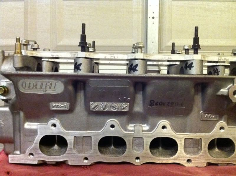
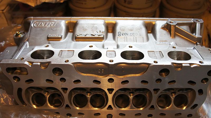
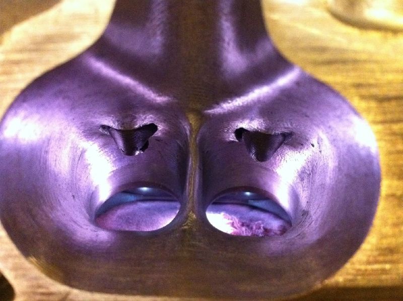
Dart took new OEM Honda P72 castings and worked their magic.
Full CNC porting on intake and exhaust runners.
The intake valves are +1mm oversized.
The combustion chambers are CNC blended.
Here are the flow specs from Dart.
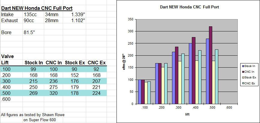
320cfm @ .500" is bad ***.
Dart stopped making these bad boys 5 or 6 years ago so they are rare.
This is pretty much a unicorn.
Dart took new OEM Honda P72 castings and worked their magic.
Full CNC porting on intake and exhaust runners.
The intake valves are +1mm oversized.
The combustion chambers are CNC blended.
Here are the flow specs from Dart.
320cfm @ .500" is bad ***.

 09-06-2012, 01:18 PM
#31

Wow nice find a Dart head, super rear and a killer head. Endyn is the only other compay that does head work on that level IMO. And going on a Benson block too boot. I like the GSR block with the Ls crank. The LS crank is key to increasing the TQ the motor can make. Will be following along.
09-06-2012, 06:16 PM
#32
Honda-Tech Member

I'm curious how the JG Edlebrock head compares to the Dart or Endyn now because that's what my buddy is using.
09-06-2012, 08:15 PM
#35
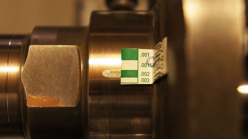
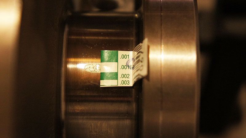
I started working on the bearings. In the past I only used Honda OEM bearings for the different sizes but they are expensive and I’m not convinced they are any better. I can get a complete set of ACLs (mains and rods) for $100. In my previous engine I used a combination of ACLs where I could and OEMs where I needed a different thickness. And later when I tore it down the ACL bearings looked just as good as the OEM bearings. So this time I will keep it simple and go with ACL Race bearings.
Factory service manual for a B18C1 calls for:
Mains 1, 2, 4, 5: .0009 ~ .0017”
Main 3: .0012 ~ .0019”
Rods: .0013 ~ .0020”
In my previous motors I targeted .0015” for main and rod bearing clearances because it was an easy round number to measure for. And this time I wanted to go with looser clearances towards the big end of the range.
My new target clearances:
Mains 1, 2, 4, 5: .0017”
Main 3: .0019”
Rods: .0020”
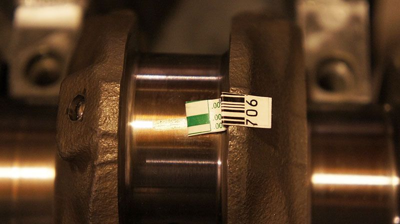
The main bearings are all really tight with the new crank. I won’t bore everyone with pictures of this stage.
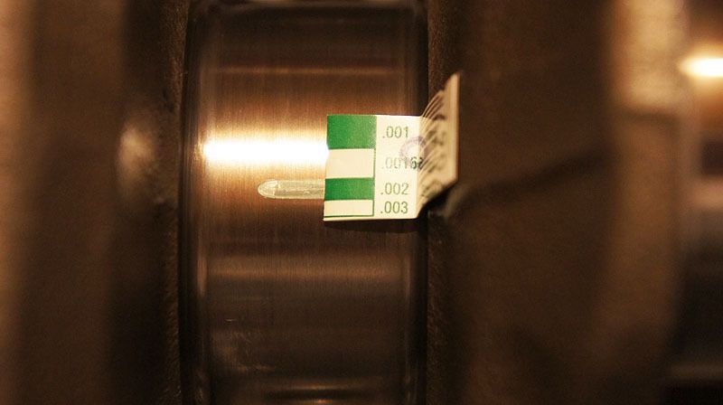
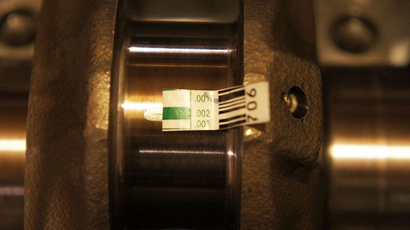
Clearances with ACL Race STD:
Main 1: .0010”
Main 2: .0010”
Main3: .0012”
Main4: .0010”
Main5: .0010”
Rods: .0010”
These are way too tight! I am going to need the thinnest bearings available. After some research it turns out ACL Race bearings come in a XTR size which is supposed to give .0010” additional clearance so I ordered a set.
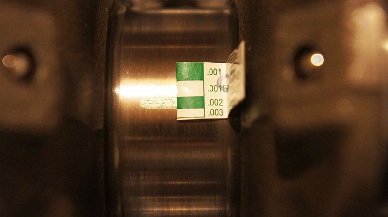
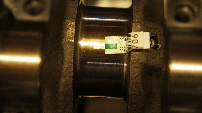
Clearances with ACL Race XTR:
Main 1: .0015”
Main 2: .0018”
Main3: .0020”
Main4: .0018”
Main5: .0015”
Rods: .0015”
Mains 1 and 5 are still too tight and the rods are still way off. This is the thinnest bearing on the market so machine work is required to get the clearances I want. I need the rods honed and the crank turned. A lot of people say you can’t turn a Honda crank because they are nitrided and this layer will be removed. This is not true. The nitriding process can be as deep as .0020” so taking half a thousandth is no problem. The alternative to turning the crank is a line hone of the mains. This can be very problematic and expensive. Because the mains caps are steel and the block is aluminum any machine work is going to cut more into the softer aluminum. This moves the center line up and in turn my piston to deck height will be reduced. I can’t afford to risk this as my block has been decked 5 times before. A line hone will also make sure the crank journals are in a perfect line but I’m positive mine is OK as I’ve never had any main bearing issues or uneven wear before.
Factory service manual for a B18C1 calls for:
Mains 1, 2, 4, 5: .0009 ~ .0017”
Main 3: .0012 ~ .0019”
Rods: .0013 ~ .0020”
In my previous motors I targeted .0015” for main and rod bearing clearances because it was an easy round number to measure for. And this time I wanted to go with looser clearances towards the big end of the range.
My new target clearances:
Mains 1, 2, 4, 5: .0017”
Main 3: .0019”
Rods: .0020”
The main bearings are all really tight with the new crank. I won’t bore everyone with pictures of this stage.
Clearances with ACL Race STD:
Main 1: .0010”
Main 2: .0010”
Main3: .0012”
Main4: .0010”
Main5: .0010”
Rods: .0010”
These are way too tight! I am going to need the thinnest bearings available. After some research it turns out ACL Race bearings come in a XTR size which is supposed to give .0010” additional clearance so I ordered a set.
Clearances with ACL Race XTR:
Main 1: .0015”
Main 2: .0018”
Main3: .0020”
Main4: .0018”
Main5: .0015”
Rods: .0015”
Mains 1 and 5 are still too tight and the rods are still way off. This is the thinnest bearing on the market so machine work is required to get the clearances I want. I need the rods honed and the crank turned. A lot of people say you can’t turn a Honda crank because they are nitrided and this layer will be removed. This is not true. The nitriding process can be as deep as .0020” so taking half a thousandth is no problem. The alternative to turning the crank is a line hone of the mains. This can be very problematic and expensive. Because the mains caps are steel and the block is aluminum any machine work is going to cut more into the softer aluminum. This moves the center line up and in turn my piston to deck height will be reduced. I can’t afford to risk this as my block has been decked 5 times before. A line hone will also make sure the crank journals are in a perfect line but I’m positive mine is OK as I’ve never had any main bearing issues or uneven wear before.
09-06-2012, 08:30 PM
#36
i HAS questions ?
Join Date: Feb 2003
Location: OH
Posts: 7,850
Likes: 0
Received 0 Likes
on
0 Posts
09-06-2012, 08:55 PM
#38
Honda-Tech Member

In the damaged #4 pics, it looks like the piston made contact with the head as a result of the bearing going out. The clearance goes away and it tapped the head very lightly. The marks on the piston directly correspond to the chamber edges and squish area.
The following users liked this post:
 09-07-2012, 02:38 AM
#41
Honda-Tech Member
Join Date: Oct 2004
Location: Mid East Deserts
Posts: 1,073
Likes: 0
Received 0 Likes
on
0 Posts
My new target clearances:
Mains 1, 2, 4, 5: .0017”
Main 3: .0019”
Rods: .0020”
I need the rods honed and the crank turned. A lot of people say you can’t turn a Honda crank because they are nitrided and this layer will be removed. This is not true. The nitriding process can be as deep as .0020” so taking half a thousandth is no problem.

It's exactly the same clearances with what I did on the first two builds I made since '09. I did turn the crank too to get me to my preferred clearances while using ACL standard(non race) bearings.
09-07-2012, 05:23 AM
#45
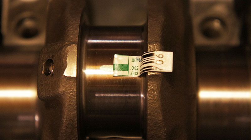
The machine shop wasn’t able to take as much off of main journal #5 as I requested. They said it was in danger of becoming out of round. I don’t understand how taking a few tenths is fine but a few more and it would get out of round but who am I to argue. I needed half a thousandths extra clearance on the rods so they split the difference between the rod and the journals. Very good customer service there and quick turn around times. This cost me $110.
Material removed:
Rod big ends: +.0002 ~ 0003”
Rod journals: -.0002 ~ 0003”
Main journal #1: -.0002”
Main journal #5: -.0005”
Main1 new clearance: A little less than .002”, we’ll call it .0018
Main2 new clearance: .002”
Main3 new clearance: .002”
Main4 new clearance: .002”
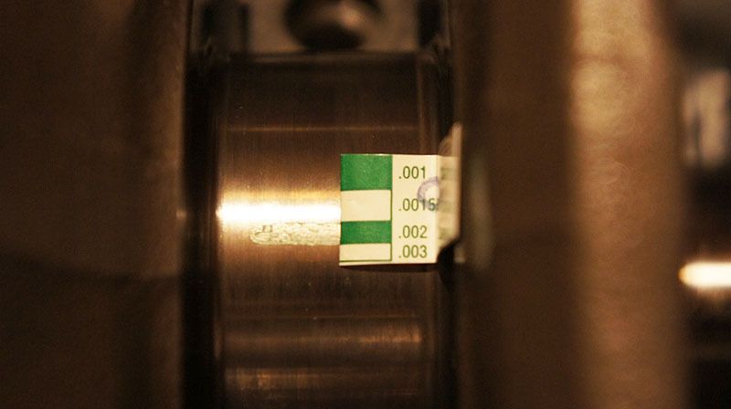
Main5 new clearance: .0015”, I had hoped for closer to 20 but 15 ten thou will do.
Rod1 new clearance: .002”
Rod2 new clearance: .002”
Rod3 new clearance: .002”
Rod4 new clearance: .002”
Main5 is the only clearance that concerns me. It was about .0015 before machine work and its .0015” after machine work. Maybe it’s the plastigage, but I remeasured it 10 times. However its in factory spec and the last journal can be a little tighter than the rest so it'll do.
Material removed:
Rod big ends: +.0002 ~ 0003”
Rod journals: -.0002 ~ 0003”
Main journal #1: -.0002”
Main journal #5: -.0005”
Main1 new clearance: A little less than .002”, we’ll call it .0018
Main2 new clearance: .002”
Main3 new clearance: .002”
Main4 new clearance: .002”
Main5 new clearance: .0015”, I had hoped for closer to 20 but 15 ten thou will do.
Rod1 new clearance: .002”
Rod2 new clearance: .002”
Rod3 new clearance: .002”
Rod4 new clearance: .002”
Main5 is the only clearance that concerns me. It was about .0015 before machine work and its .0015” after machine work. Maybe it’s the plastigage, but I remeasured it 10 times. However its in factory spec and the last journal can be a little tighter than the rest so it'll do.
09-07-2012, 05:36 AM
#46
Honda-Tech Member
09-07-2012, 05:56 AM
#47
Honda-Tech Member
Have you tried giving the bearings a real good clean down Muckman? I used a small square of folded newspaper soaked in "3in1 oil" and lightly scrubbed the bearings back and forth until they were shinny before checking the clearances.
09-07-2012, 06:32 AM
#48
Yes I cleaned the main, the journal and the bearing repeatedly. I even tried swapping bearings. I mic all of them and used the thinnest bearing. There really was no difference, maybe a ten thou between them. I just left it alone.
09-07-2012, 06:33 AM
#49
Honda-Tech Member
The "dull" coating is there for a reason....
09-07-2012, 09:05 AM
#50
Ring gap, like bearing clearance, is debatable and varies from builder to builder. With more gap comes more blow by and power loss. But if the ring gap is not big enough the ends will butt from thermal expansion and you will crack the ring lands. So it’s a balance. Ideally you want as little gap as you need. The piston manufacturers provide a ring gap sheet with a formula to calculate the gap. It’s always bore times a multiplier and the multiplier depends on the application.
In my previous engine I used a multiplier of .006 for the top ring and .0065 for the 2nd rings. This time I plan on making more power so I’m going to use multipliers of .0065 for top and .007 for the 2nd ring.
3.3268” x .0065 = .0216 I rounded up to .022” for top ring
3.3268” x .0070 = .023” for the 2nd ring.
The problem I’ve encountered with 2nd rings is they come too large unfiled from the factory. My first ring pack had 2nd rings that were larger than my target of .023” so I had then send me another pack and they ended up all being .022 unfiled. That works for me but would suck if I was using a smaller multiplier, ie N/A. The theory is the 2nd ring gap is not as important as the top ring but it’s critical that it’s larger than the top ring to prevent ring flutter.
The oil rings are not supposed to be touched. They just need to be a minimum of .015”.
Summit Racing ring filer clamped to my table
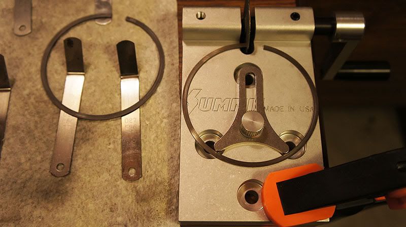
Filing the rings can be tricky. You want to make sure you file them perfectly square along 2 axes. The sanding disc is perpendicular to the tool so that takes care of 1 axis automatically. I found that if you press the ring against the wheel too hard the ring will flex outward causing it to file on a slight angle. I can’t imagine filing rings without a good ring filer. This ends up being an excise in patience. You need to take your time and make many small passes because you don’t want to file past the target gap. I may make as many as 10 passes on each ring while measuring in between.
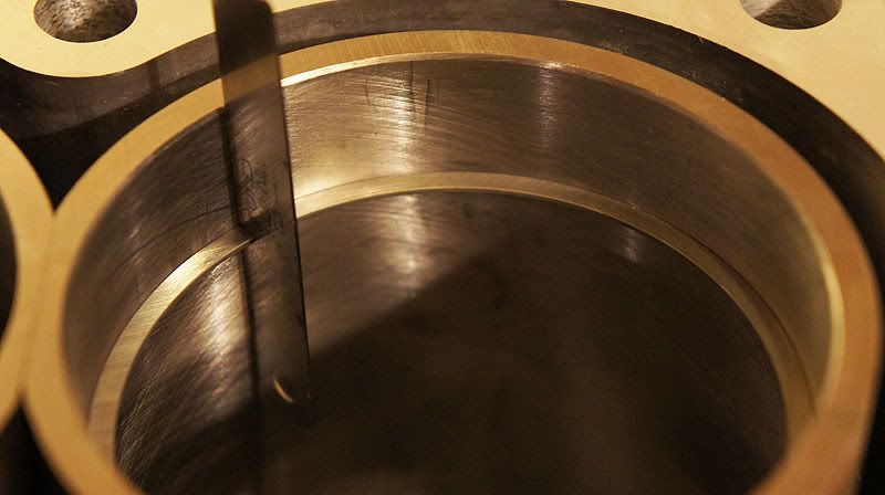
Using an old piston to square up the rings in the cylinder. You can use the new piston too. I just used an older one so I didn’t scratch up the ceramic coating on my new pistons.
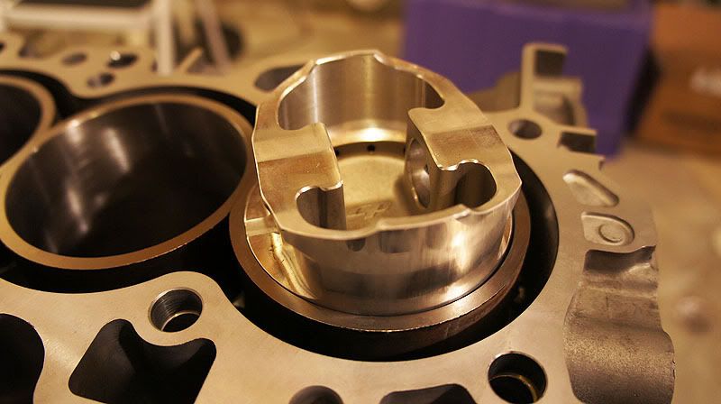
Ring all squared up in the hole and ready to be measured.
Using feeler gauge to measure the ring gap.
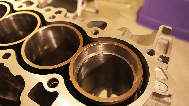
When you are finished with the ring gaps the ends should be deburred so they can move freely and not scratch the cylinder wall as you can see mine already have. You can use a deburring tool or fine sand paper. I use a sharpening stone because it’s easier to keep flat.
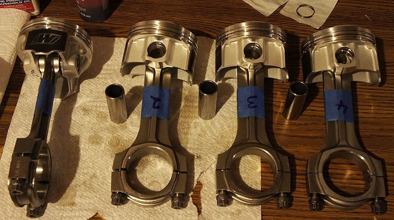
Getting the wrist pins installed. #4 rod is the new one from Pauter. The rest are reused.
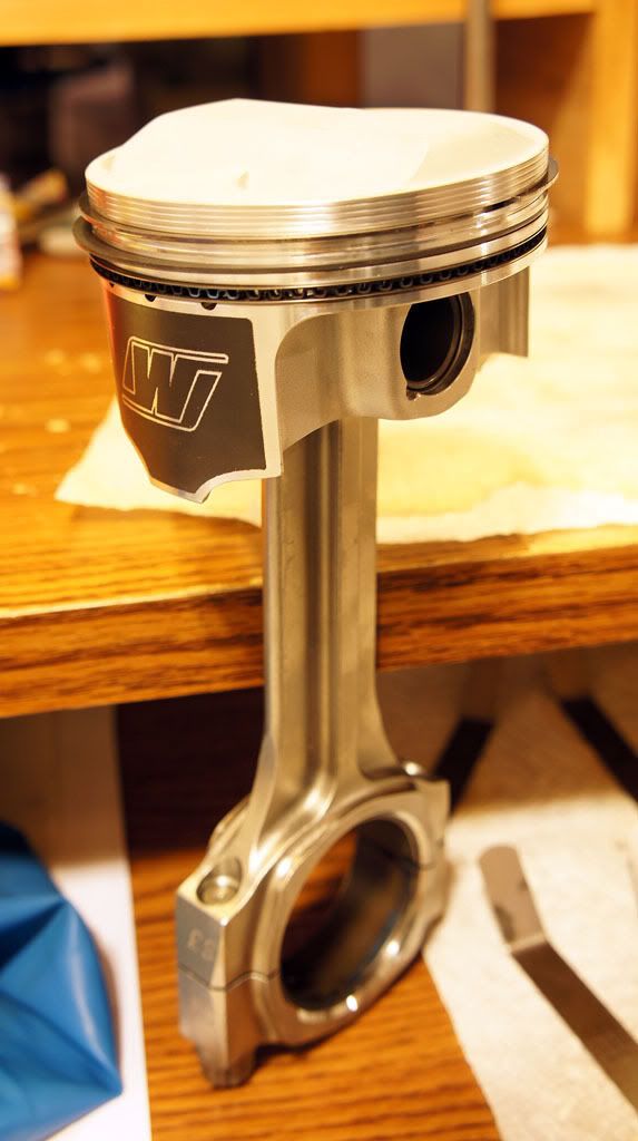
Piston assembled with the rings clocked.
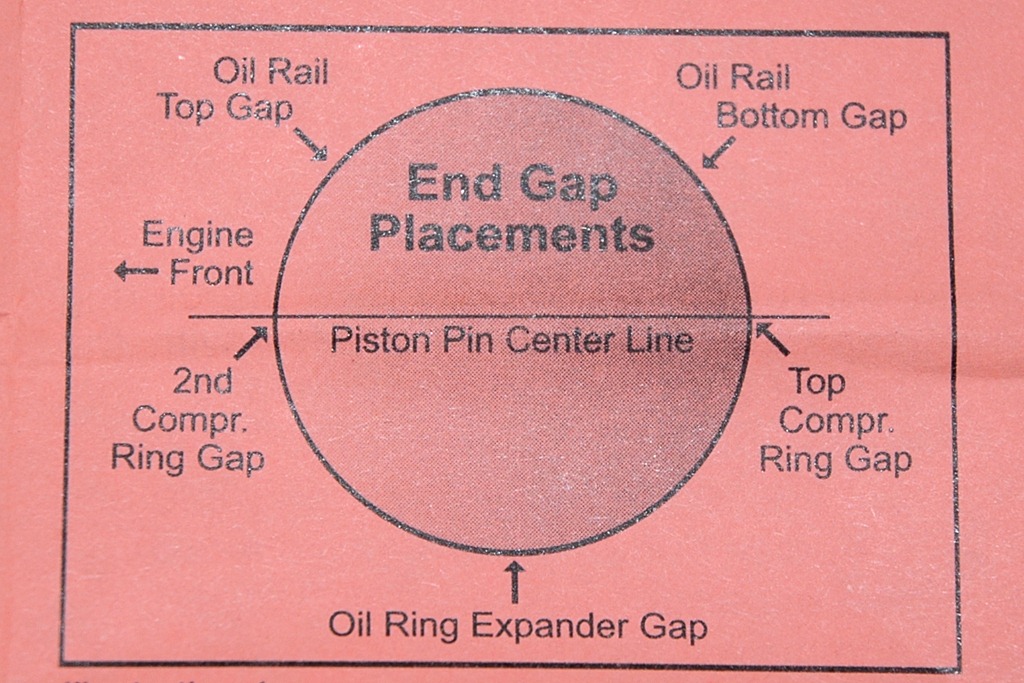
I used this method to clock the end gaps. However "Engine Front" does not mean the exhaust side. It means towards Cylinder #1 - Driver side. When clocking the rings you want the top and 2nd rings to be 180* of each other so there isn’t a straight path for gases to blow by but you don’t want any of the ring gaps to be on a thrust axis either.
Next up short block assembly!
In my previous engine I used a multiplier of .006 for the top ring and .0065 for the 2nd rings. This time I plan on making more power so I’m going to use multipliers of .0065 for top and .007 for the 2nd ring.
3.3268” x .0065 = .0216 I rounded up to .022” for top ring
3.3268” x .0070 = .023” for the 2nd ring.
The problem I’ve encountered with 2nd rings is they come too large unfiled from the factory. My first ring pack had 2nd rings that were larger than my target of .023” so I had then send me another pack and they ended up all being .022 unfiled. That works for me but would suck if I was using a smaller multiplier, ie N/A. The theory is the 2nd ring gap is not as important as the top ring but it’s critical that it’s larger than the top ring to prevent ring flutter.
The oil rings are not supposed to be touched. They just need to be a minimum of .015”.
Summit Racing ring filer clamped to my table
Filing the rings can be tricky. You want to make sure you file them perfectly square along 2 axes. The sanding disc is perpendicular to the tool so that takes care of 1 axis automatically. I found that if you press the ring against the wheel too hard the ring will flex outward causing it to file on a slight angle. I can’t imagine filing rings without a good ring filer. This ends up being an excise in patience. You need to take your time and make many small passes because you don’t want to file past the target gap. I may make as many as 10 passes on each ring while measuring in between.
Using an old piston to square up the rings in the cylinder. You can use the new piston too. I just used an older one so I didn’t scratch up the ceramic coating on my new pistons.
Ring all squared up in the hole and ready to be measured.
Using feeler gauge to measure the ring gap.
When you are finished with the ring gaps the ends should be deburred so they can move freely and not scratch the cylinder wall as you can see mine already have. You can use a deburring tool or fine sand paper. I use a sharpening stone because it’s easier to keep flat.
Getting the wrist pins installed. #4 rod is the new one from Pauter. The rest are reused.
Piston assembled with the rings clocked.
I used this method to clock the end gaps. However "Engine Front" does not mean the exhaust side. It means towards Cylinder #1 - Driver side. When clocking the rings you want the top and 2nd rings to be 180* of each other so there isn’t a straight path for gases to blow by but you don’t want any of the ring gaps to be on a thrust axis either.
Next up short block assembly!

