When you click on links to various merchants on this site and make a purchase, this can result in this site earning a commission. Affiliate programs and affiliations include, but are not limited to, the eBay Partner Network.
This will show the process in how I added an AUX input to a 1991 Honda Accord Stereo Deck. Enjoy!
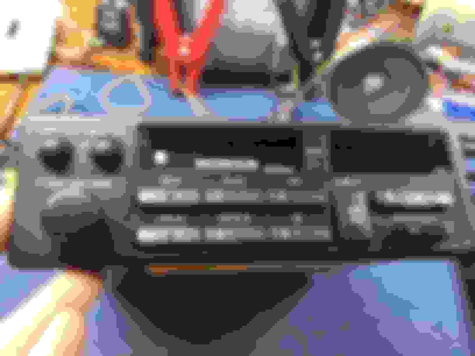
I bought a ’91 Civic Si a few months ago. At some point in its previous life the owner decided to install a cheesy aftermarket stereo. Half of it didn’t light up and the FM reception was non-existent, not to mention the quality of the buttons and screen was awful.
The old deck
I promptly removed the stereo and was surprised to see that a proper harness adapter was used, which meant I didn’t have to repair any wiring. I wanted to replace it with a factory Honda stereo for simplicity’s sake; I’m not a fan of flashy aftermarket units that scream “I don’t belong here”. The interior in my Civic is in extremely good condition and I felt it deserved an equally clean stereo.
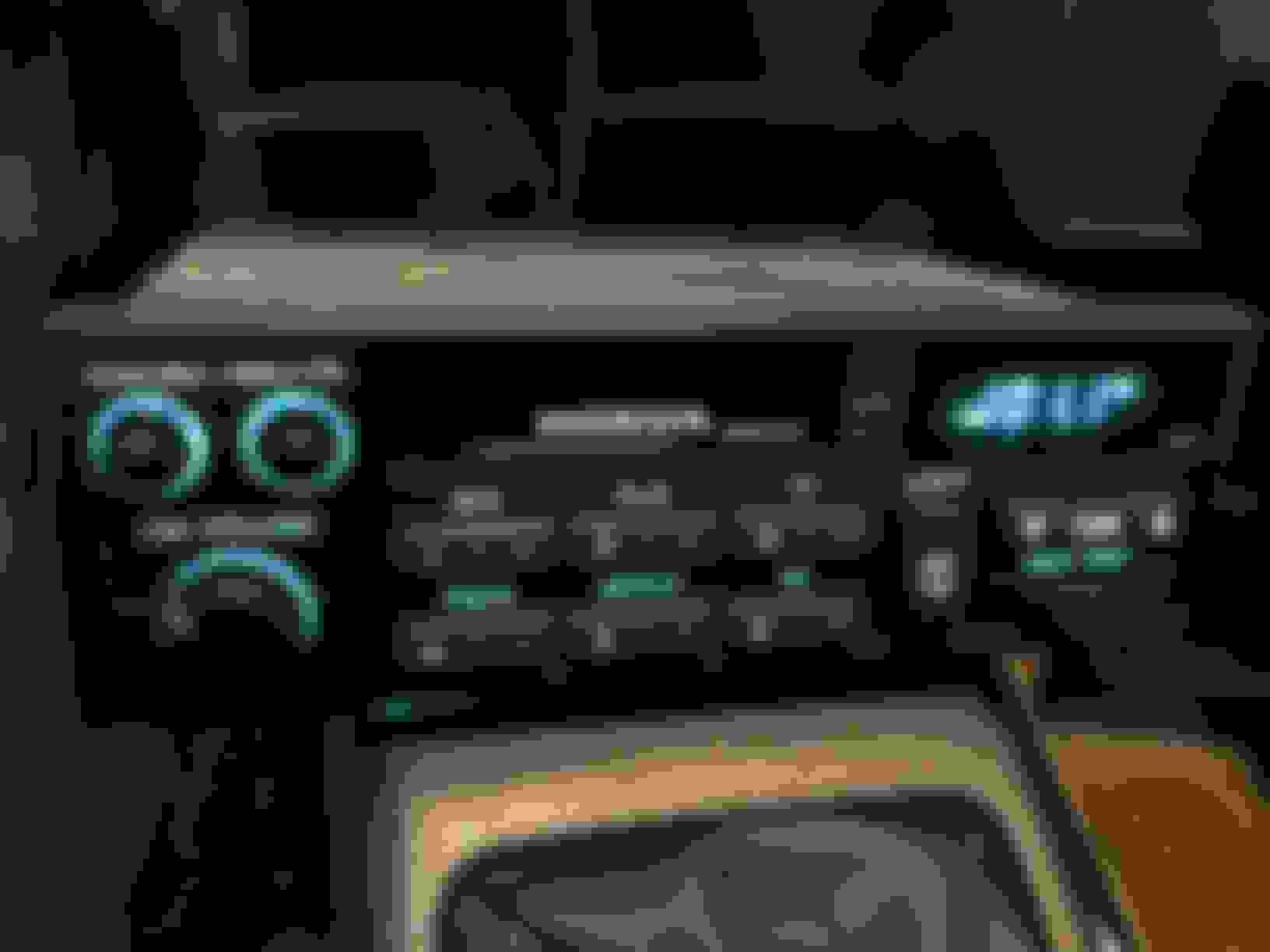
I went to the wreckers and spotted a ’91 Accord, it was parked in the crush area, presumably soon to meet its maker. I hopped in and was pleasantly surprised; it had 98,000 kms (61,000 miles) and had a near mint interior. I yanked out the deck and $20 later it was mine.
Accord Deck
I installed it in my car to ensure everything worked properly. This particular deck has the exact same mounting holes as the factory 91 Civic deck, it bolts right in, zero issues.
Everything lights up and works
Looks good in the Civic interior, blends right in
I really wanted the option of playing my iPod through my stereo. There were a few options to do this: an FM transmitter, Tape Adaptor, or an FM modulator, but I wanted nothing to do with any of these. The sound quality and consistency of these options are just not acceptable, not to mention the wires are unsightly.
FM Transmitter, Tape Adaptor and Modulator
I endeavored to find a way to modify the stereo internally to allow an AUX input. I researched this to death. It’s been done many times and oddly popular with BMW decks. The basic idea is to use an aux cord or RCA jacks and solder the wiring onto the deck circuit board to input your own signal. I found a couple videos too but those guys are on a whole other level of electronics testing. There are also a few websites I found that offer this modification as a service, though it’s costly and would involve shipping, too expensive. I decided to jump in head first and just start experimenting. Worst case scenario? I fry the deck and have to find another one, there are a lot of old Accords out there so I wasn’t overly worried.
I opened up the top of the deck, it comes off very easily. The top portion was crowded with the tape player mechanism and I really didn’t want to dig into it. Tape decks are very complicated, there are sensors and switches all over that communicate a lot of information to the deck. It knows if a tape is inserted, if both spools are spinning and in what direction, and whether anything is actually playing. Tricking the deck into thinking all of these things is not within my skill set.
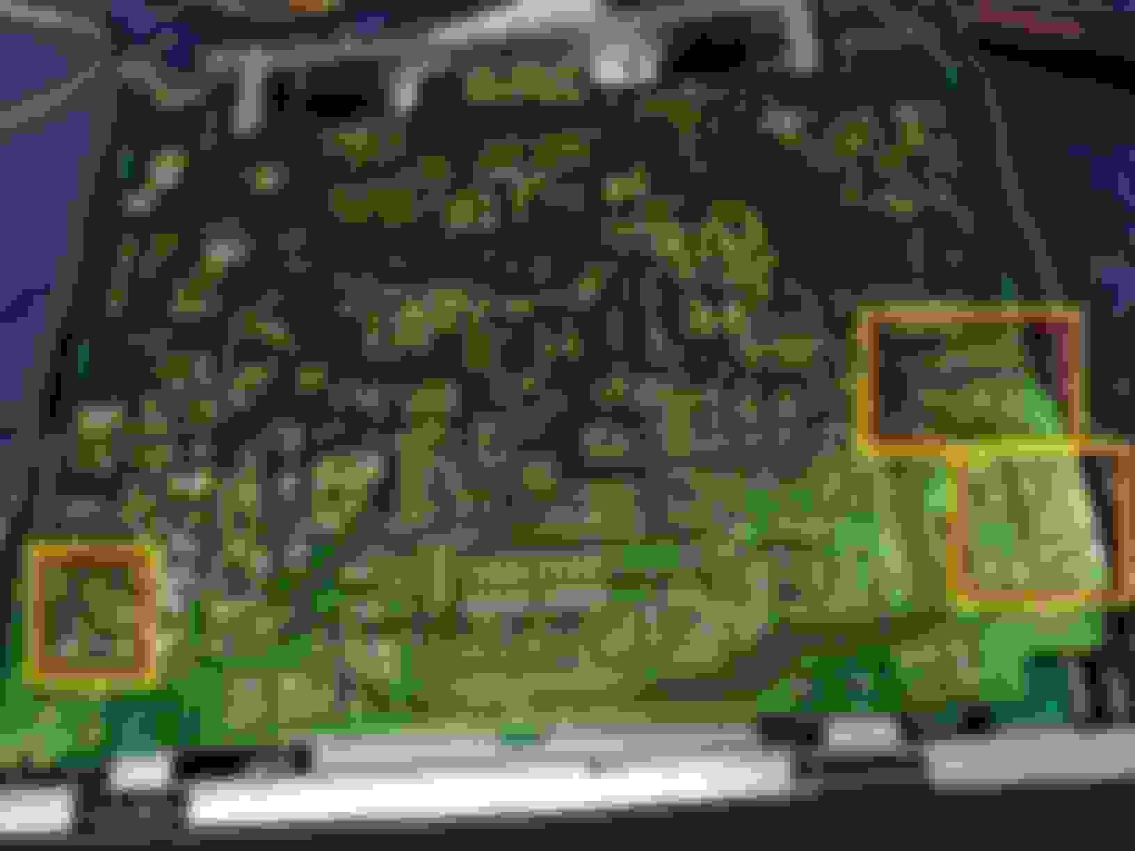
Opening the bottom of the deck was a lot more encouraging. I discovered that many of the contacts were labeled.
Bottom of board has labels for most contacts
I hacked up a spare AUX cord and used the wires to test different contacts I found on the board. It’s as simple as touching the left/right aux wires to the left in/right in contacts on the board. Clipping the AUX ground to the deck chassis worked well enough for early testing. I used my iPod to play the music which in hindsight probably wasn’t the smartest idea seeing as I could have fried it fairly easily.
I found a few different sets of labels which seemed promising. Each set had a L/R and GND.
Different circuit board inputs outlined in Red/Yellow
I tested each of them with mixed results. Testing one set resulted in very distorted playback, turning the volume down helped but I knew this one wouldn’t work. Another set worked perfectly but the volume **** had no effect, I could only control the input volume from my iPod, not ideal.
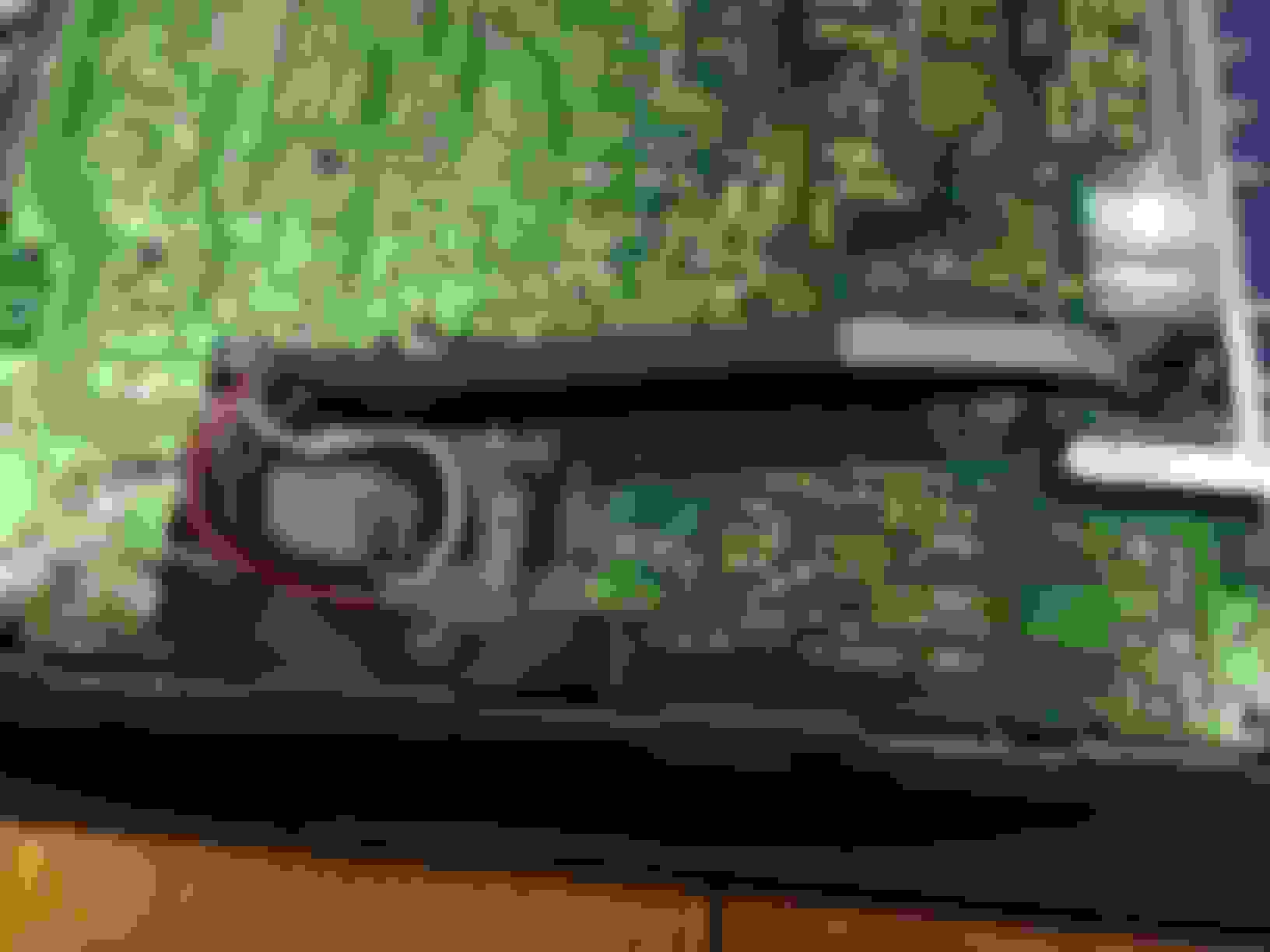
The last set I tested was the winner. I assume this set of contacts was before the volume ****, so the signal is inputted into the contacts and then goes through the volume **** circuitry and out to the speakers, which is what we want. I tested these contacts using different combinations of volumes on both my iPod and the deck to ensure clear playback.
Here are the contacts I ended up using, outlined in red. These are found on the board on the volume **** side, close to the front.
I grabbed a set of female RCA plugs from my parts bin and stripped them back. I decided against soldering an AUX cord directly to the board because I question the quality of most of the aux cords for sale these days. I was concerned that an AUX cord will eventually wear out or break. This way I can always replace the aux cord with a new one if needed, just plug it in to the RCA plugs. Another added benefit is that RCA wiring normally uses slightly thicker wiring, easier to solder.
I had to drill a hole into the back of the deck for the wiring, about �” drill bit.
Hole drilled at the back for the RCA plugs to exit.
BE SURE TO PUSH THE WIRES INTO THE DECK BEFORE STARTING ANY SOLDERING!!
ALSO, BE SURE TO SLIDE ON ANY SHRINK WRAP PRIOR TO SOLDERING!!
Wiring length shown, red, white and ground
It’s as simple as soldering each wire to its respective spot. The Red RCA wire goes to R-IN (red is right, easy). The white RCA wire goes to L-IN and the bare ground wire goes to S-GND. I bent each wire into a U-shape so I could push them onto the pins, making it easier to solder and ensuring good contact.
U shape at end of Red wire shown, white (left) and ground already soldered
I stripped a very small amount to only expose 3-4mm of each wire. You don’t want too much exposed because it may short out against another contact. It’s smart to tin the wire ends with solder to keep them from fraying as you work.
I used shrink wrap to keep things together and cover the exposed ground wire. The ground wire was fully bare, so shrink wrap was the only option.
Shrink wrap on ground wire and on whole bundle
After everything was soldered I took the precaution of electrical taping the board under the added wiring. This is probably excessive but with the vibrations of driving, you just never know what might work its way loose. Better safe than sorry.
Electrical tape shown under wiring as an extra precaution
A zip tire on the wiring ensures the wires can’t get yanked off the board by accident. Leave a little slack in the wiring as another precaution.
Zip tie on the wiring prevents any accidental tugs from damaging your work
Button it all back up again and you’re done!
All done and re-assembled
So, how does it work? The best part of this modification is that as soon as you plug in the AUX cord, the radio automatically turns off, even if you don’t have anything playing on your iPod. As soon as you unplug your iPod, the radio comes back on instantly. No switches or extra buttons needed.
I did notice that at high volume there is a very small amount of radio signal that leaks through in AUX mode, an easy fix to this is to just set the radio to a station that has no signal.
And just to illustrate my commitment to getting this done...
This was my work table once I was done
Thanks for reading!
Here's some more info on this specific deck in case one of you folks want to take this project on yourselves. It's a nice deck and I highly recommend it for anyone looking for an older OEM deck.
Last edited by kp; 02-12-2016 at 08:57 AM.
Reason: Formatting
Nice write-up, however why go to all the trouble when the HU has a sig. in/out, for EQ, "Din Socket"??? 94
I thought the same thing. From what I recall, those DIN sockets are proprietary to each manufacturer and tapping into it is near impossible without having the "magic formula". Newer decks have aftermarket adaptors to do exactly what you're saying.
If you can figure out how to do it with an older deck like this, let me know.
The only thing proprietary about it is the "Din" configuration, if you pull the plug you will see 4 metal pins in the plug, they are jumpers, signal out/signal in.
Do not confuse that Din plug with the CD controller input on some Honda/Acura head units, the CD changer input does not have a jumper plug in it.
If you are talking about a CD changer input, there are more then a few adpt. out there to convert it into an AUX input.
The head unit posted is not a CD controller it has the port for the EQ as indicated by the white plug in the port. 94
Have you found any supporting pictures/articles/diys that show what you're explaining? I did some considerable research before cracking this thing open and the EQ plug was never mentioned.
Another potential complication would be how to switch between the aux and radio. If the aux signal was fed through the port input, the radio signal would be cut off. Hmmm.
I found a picture of the EQ pins, any idea of the pinouts?
Yes a "bypass" switch would need to be installed, it would solve the problem of radio coming through at high volume, as now you have both the aux. signal and radio signal going to the input.
Its been a while so I can not remember the pinout, I will have to check, but if you unplug the white jumper you should find 4 pins and I think input is pins 3 and 5, with 4 being sig. return/ground, pin 1 would be first one clockwise from the "clocking" divot.
I will see if I can dig out my service manual for the Honda HUs 94
This is interesting, I appreciate your comments on this. I may need to revisit this if there's a cleaner way (and potentially better audio quality).
Sorry, I can not find my Honda HU service manual, but it would be easy to find, unplug the white jumper, touch a signal, it can be any signal even a pos signal from a AAA bat. the neg. of the batt . goes to the HU chassis, the speakers will "pop" when you have the inputs. 94
This is a great idea! I tried this over the weekend with an old deck and it worked! Only problem is that it only worked for the left side. Music came out the left side, but the right did not play and the rear speakers did not play either. Are the rear speakers supposed to come on or do you need to wire the aux plugs to the rear as well?
This is a great idea! I tried this over the weekend with an old deck and it worked! Only problem is that it only worked for the left side. Music came out the left side, but the right did not play and the rear speakers did not play either. Are the rear speakers supposed to come on or do you need to wire the aux plugs to the rear as well?
The AUX cord has a left wire and a right wire, I made my connections to the left and right channels on the circuit board. You should recheck your right channel connection. It's my understanding that the rears should come on with the fronts (same signal with these old decks).
i think there is a few ebay members that do this. i know just from one of my random searches for car parts the other day lol
Lol, that's awesome! You would happen to have a link by chance would you? I just realized that all the attention I've put into my swap, my radio sucks! I need to be listening to anything but the radio.
I've very interested. I don't trust myself with soldiering anything.
Excellent write up! I'm in the process of creating a soundboard/synthesizer by hooking up a Raspberry Pi to a $20 12v PA system. The level of detail you provided confirmed I'm heading with the right wiring approach (PA has no external input either). Thank you for sharing!

 02-11-2016, 09:57 AM