
Australian GSR
 07-01-2014, 08:39 AM
#26
 07-01-2014, 06:36 PM
#27
Honda-Tech Member
Thread Starter
Join Date: Jun 2014
Location: Australia
Posts: 83
Likes: 0
Received 0 Likes
on
0 Posts
On one run I dropped a wheel completely over the ripple strip, the back side of which had been worn away by other cars doing the same thing.
The car jumped the ripple strip with a bit of a bang but I didn't think much of it.
I found the twisted UCA when I had the car up on the hoist the next day.
07-02-2014, 04:04 AM
#28
Cool Cool Island Breezes. BOY-EE
iTrader: (1)
Join Date: Sep 2006
Location: TRILLINOIS....WAY downtown, jerky.
Posts: 11,953
Likes: 0
Received 4 Likes
on
4 Posts
Each run of HH I tried to straightening up my line into this uphill sweeping left hander.
On one run I dropped a wheel completely over the ripple strip, the back side of which had been worn away by other cars doing the same thing.
The car jumped the ripple strip with a bit of a bang but I didn't think much of it.
I found the twisted UCA when I had the car up on the hoist the next day.
On one run I dropped a wheel completely over the ripple strip, the back side of which had been worn away by other cars doing the same thing.
The car jumped the ripple strip with a bit of a bang but I didn't think much of it.
I found the twisted UCA when I had the car up on the hoist the next day.
07-04-2014, 03:32 AM
#29
Honda-Tech Member
Thread Starter
Join Date: Jun 2014
Location: Australia
Posts: 83
Likes: 0
Received 0 Likes
on
0 Posts
Possibly! I don't actually know what spring rates the Tanabe struts came with. Its on my list of things to measure as it's pretty fundamental to car set up.
 07-05-2014, 10:02 PM
#31
Honda-Tech Member
Thread Starter
Join Date: Jun 2014
Location: Australia
Posts: 83
Likes: 0
Received 0 Likes
on
0 Posts
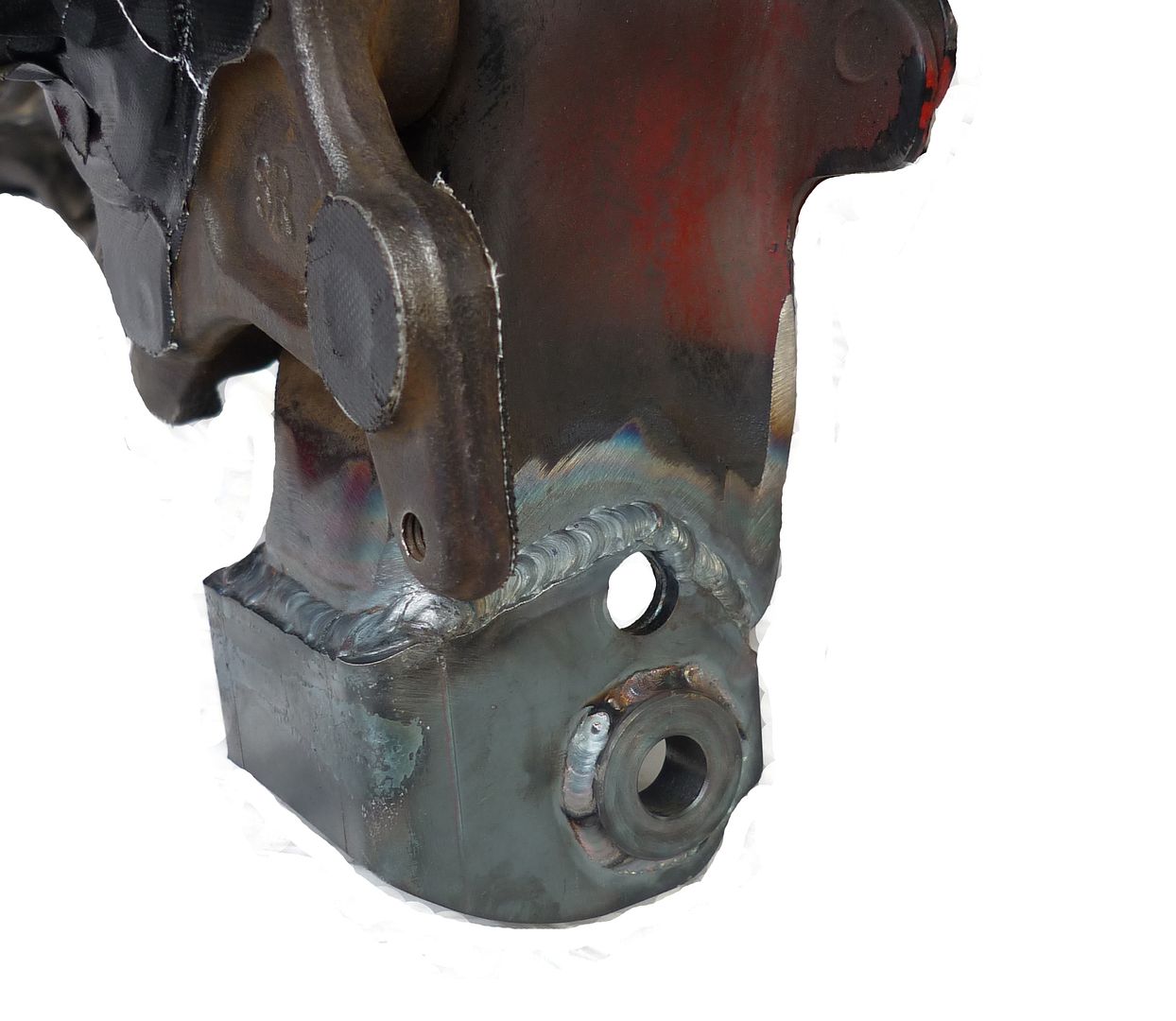
Over the weekend I completed the modifications to the trailing arms.
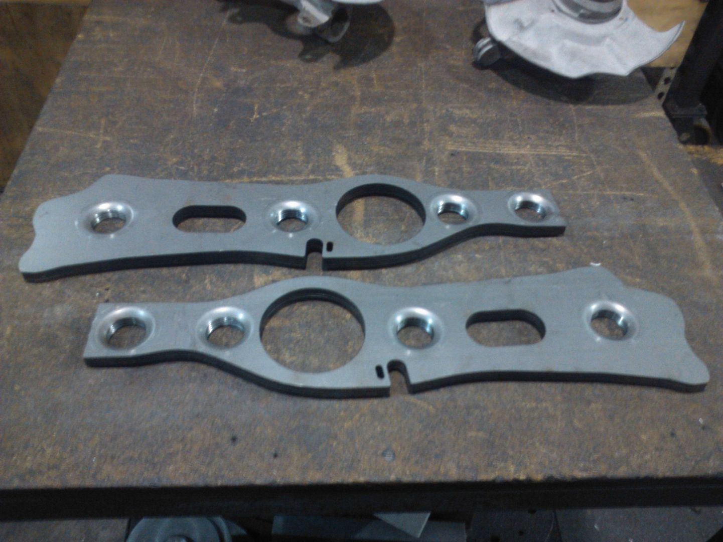
Here you can see how we stitched the trailing arm gusset to the inside of the OEM RTA.
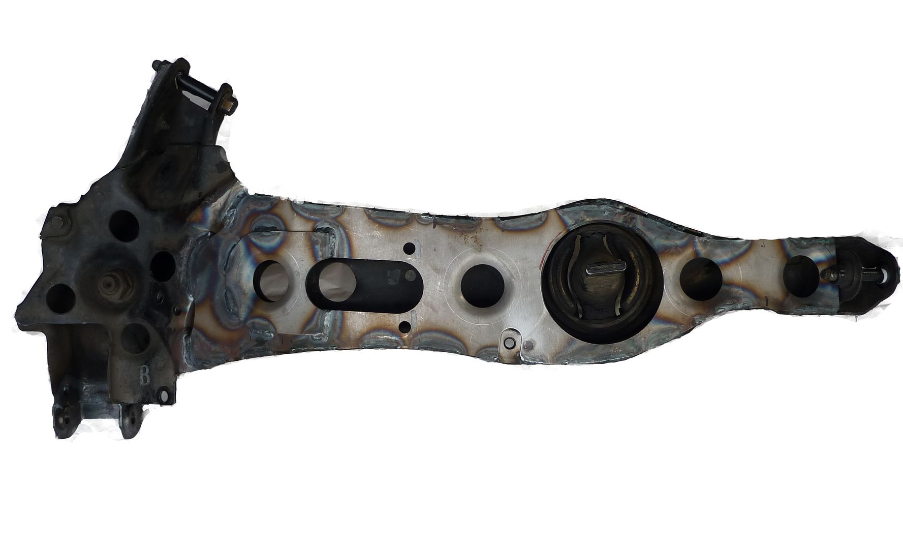
I mocked up a trailing arm with the hub and brake installed to check the routing of the handbrake cable. I found that i could squeeze the handbrake cable into place even with the "bolt on gusset" installed, to keep it easy i decided to change the design to one piece and just weld the secondary plate on for my trailing arms. I've refined the profile and plan to get a few extra sets made up.
The relocation of the LCA mounting point worked out really well.
I've got the RTA's masked up ready for sandblasting on Monday. I'll be getting them powder coated gloss black and should be pressing the new bushes in at the end of next week!
I've ordered a set of the Mfactory extended balljoints for the front knuckles
I'm well on the way to having my suspension geometry sorted out, i'm starting to get pretty excited about testing the new set up!
Here you can see how we stitched the trailing arm gusset to the inside of the OEM RTA.

I mocked up a trailing arm with the hub and brake installed to check the routing of the handbrake cable. I found that i could squeeze the handbrake cable into place even with the "bolt on gusset" installed, to keep it easy i decided to change the design to one piece and just weld the secondary plate on for my trailing arms. I've refined the profile and plan to get a few extra sets made up.

The relocation of the LCA mounting point worked out really well.
I've got the RTA's masked up ready for sandblasting on Monday. I'll be getting them powder coated gloss black and should be pressing the new bushes in at the end of next week!
I've ordered a set of the Mfactory extended balljoints for the front knuckles
I'm well on the way to having my suspension geometry sorted out, i'm starting to get pretty excited about testing the new set up!
Last edited by DailyTrackDc2; 09-12-2016 at 01:46 AM.
07-11-2014, 10:15 PM
#32
Honda-Tech Member
Thread Starter
Join Date: Jun 2014
Location: Australia
Posts: 83
Likes: 0
Received 0 Likes
on
0 Posts
bit of a tame update today,
I got the RTA's sandblasted and powdercoated during the week. Today I replaced the RTA bushes with OEM rubber items.
I'm really happy with how the RTA's have turned out. I'll take some clear photos when I get the chance.
I took the opportunity to measure the RTA with the co-ordinate measurement machine, i love this thing!
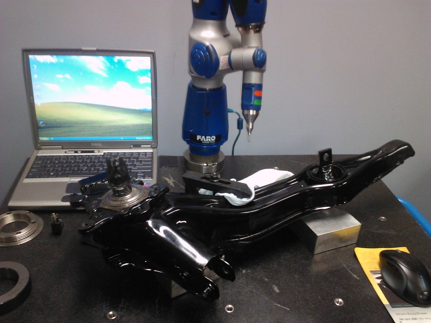
The CMM allows the operator to measure anything within it's working volume to 0.1mm.
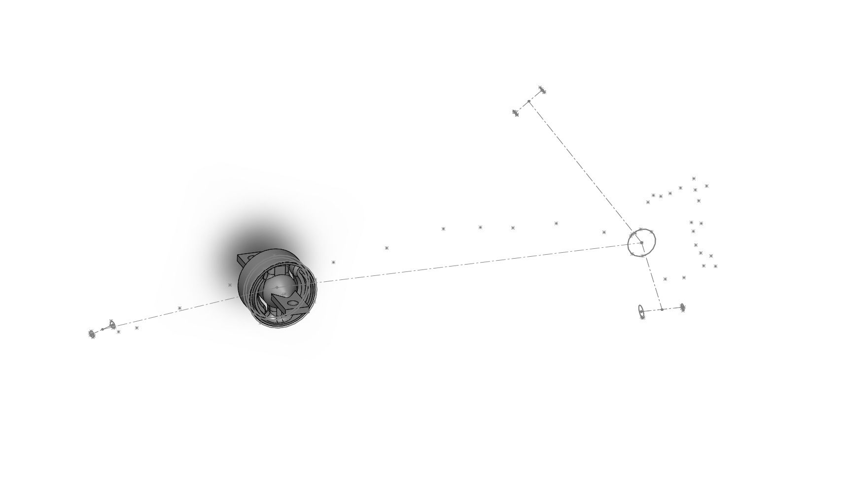
I have imported the points to SW and will update my geometry in Susprog with the more accurate dimensions for the RTA. I super imposed the new points over what I measured with the tape measure and was happy to see most points lined up.
The Mfactory front ball joints haven't arrived yet, this has given me time to arrange a few other jobs while I have the front suspension apart
I've made the decision to replace my front wheel studs and wheel bearings while I have the knuckles off.
The impact that bent the left side upper control arm also bent the top of the knuckle so i'll be replacing that entire upright.
I've acquired a set of stainless cv boot clips and plan to strip the front axles down, clean everything, then rebuild them with Redline CV-2 high temp CV grease.
Here's the plot of Toe vs Wheel travel for the front wheel, with the standard suspension geometry lowered to my current ride height (ie not super slammed). Toe in is to the right hand side of the vertical axis.
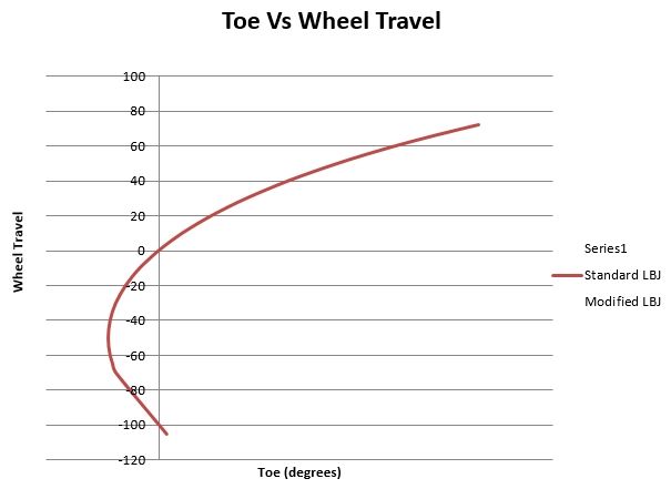
You can see the wheels toe in as soon as the front suspension goes into bump. Generally FWD cars like a bit of toe out on the front as it reduces understeer and makes the car more sensitive to driver input.
We can align the car with static toe out but going too far can cause the car to be twitchy under brakes and darty on the straights at high speed.
I'm going to try find a set up where I can get the car to toe out in bump so I can run minimal static toe out.
I got the RTA's sandblasted and powdercoated during the week. Today I replaced the RTA bushes with OEM rubber items.
I'm really happy with how the RTA's have turned out. I'll take some clear photos when I get the chance.
I took the opportunity to measure the RTA with the co-ordinate measurement machine, i love this thing!

The CMM allows the operator to measure anything within it's working volume to 0.1mm.
I have imported the points to SW and will update my geometry in Susprog with the more accurate dimensions for the RTA. I super imposed the new points over what I measured with the tape measure and was happy to see most points lined up.

The Mfactory front ball joints haven't arrived yet, this has given me time to arrange a few other jobs while I have the front suspension apart
I've made the decision to replace my front wheel studs and wheel bearings while I have the knuckles off.
The impact that bent the left side upper control arm also bent the top of the knuckle so i'll be replacing that entire upright.
I've acquired a set of stainless cv boot clips and plan to strip the front axles down, clean everything, then rebuild them with Redline CV-2 high temp CV grease.
Here's the plot of Toe vs Wheel travel for the front wheel, with the standard suspension geometry lowered to my current ride height (ie not super slammed). Toe in is to the right hand side of the vertical axis.

You can see the wheels toe in as soon as the front suspension goes into bump. Generally FWD cars like a bit of toe out on the front as it reduces understeer and makes the car more sensitive to driver input.
We can align the car with static toe out but going too far can cause the car to be twitchy under brakes and darty on the straights at high speed.
I'm going to try find a set up where I can get the car to toe out in bump so I can run minimal static toe out.
Last edited by DailyTrackDc2; 09-12-2016 at 01:46 AM.


 07-18-2014, 04:00 AM
#35
Honda-Tech Member
Thread Starter
Join Date: Jun 2014
Location: Australia
Posts: 83
Likes: 0
Received 0 Likes
on
0 Posts
I did a bit of wheeling and dealing and got myself a set of dc2 uprights to rebuild. It wasn't until I got home from the seller's place that I noticed the uprights were from a non-abs GSI model dc2. Dam!
I did a bit of research and found the ABS system in the early Dc2's is basic enough that I won't compromise the braking performance of the car by removing it.
Removing the ABS will give me part of the weight reduction over the front axle i'm looking for.
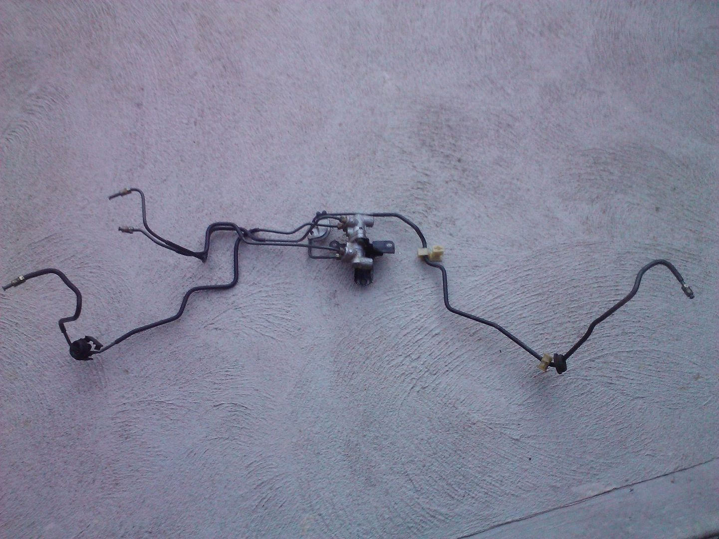
I called the seller up and sure enough he still had the complete set of hardlines from the GSI including the 40/40 bias valve. I convinced him to throw in the hardlines as otherwise the uprights were no good to me.
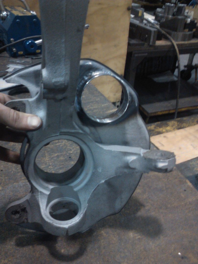
So i've stripped the uprights and had them sand blasted
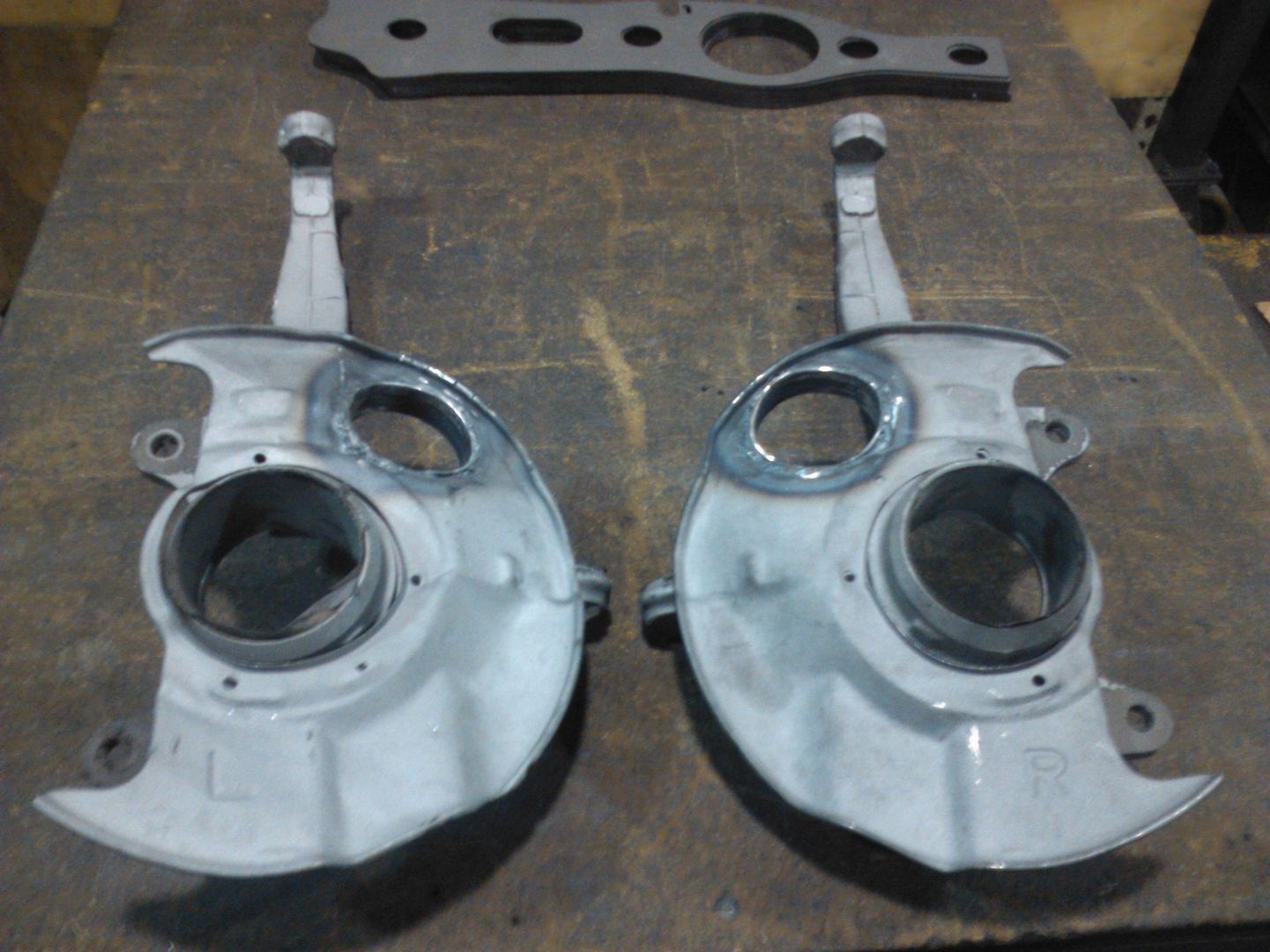
I took the opportunity to weld in a 63mm tube section into the rotor shield. In the future i will duct cold air to from the air dam to the rotors
Something like what this guy is running on his S2000
Cut hole in rotor shield
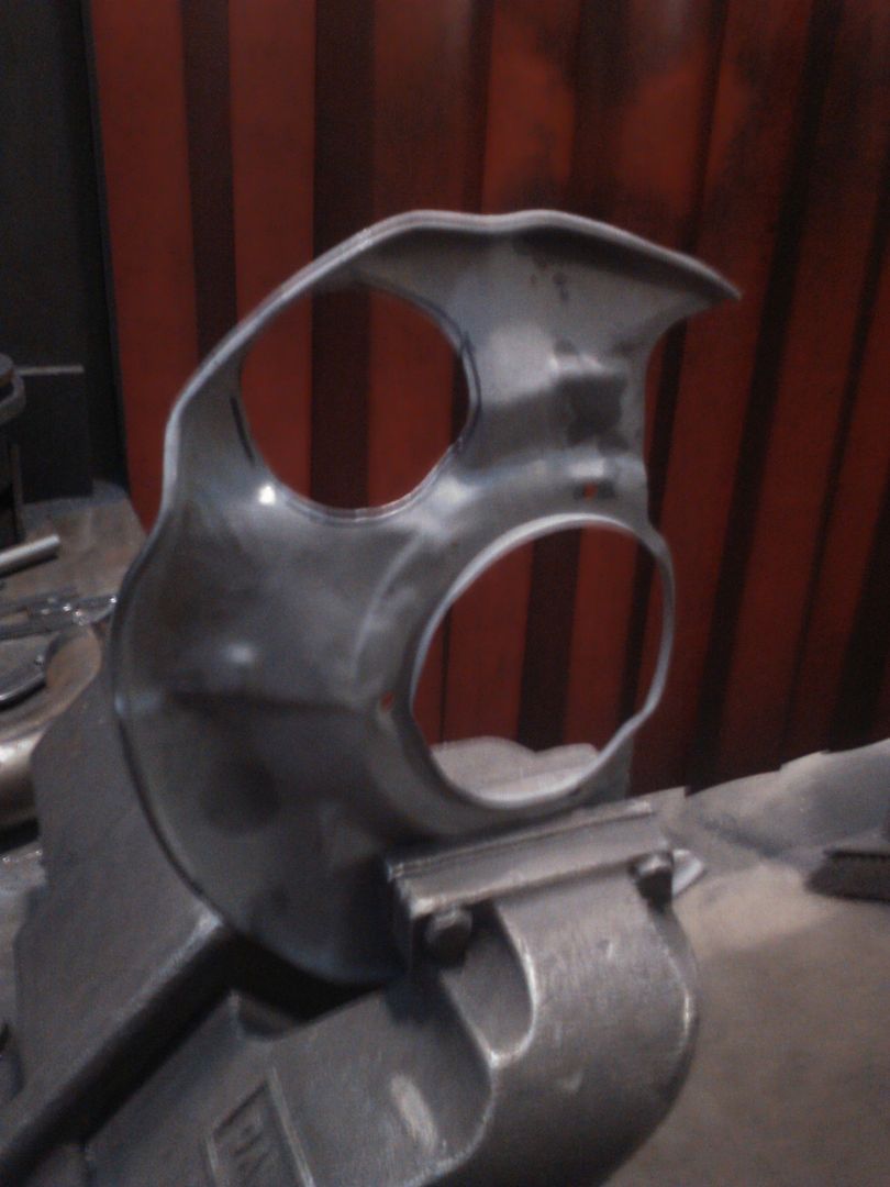
Weld 63mm tube into the hole as shown.
I've made up five sets of RTA gussets
I did a bit of research and found the ABS system in the early Dc2's is basic enough that I won't compromise the braking performance of the car by removing it.
Removing the ABS will give me part of the weight reduction over the front axle i'm looking for.
I called the seller up and sure enough he still had the complete set of hardlines from the GSI including the 40/40 bias valve. I convinced him to throw in the hardlines as otherwise the uprights were no good to me.

So i've stripped the uprights and had them sand blasted

I took the opportunity to weld in a 63mm tube section into the rotor shield. In the future i will duct cold air to from the air dam to the rotors
Something like what this guy is running on his S2000

Cut hole in rotor shield

Weld 63mm tube into the hole as shown.

I've made up five sets of RTA gussets
 07-22-2014, 12:58 AM
#36
Honda-Tech Member
Thread Starter
Join Date: Jun 2014
Location: Australia
Posts: 83
Likes: 0
Received 0 Likes
on
0 Posts
Short midweek update:
I spent Sunday converting the car to non Abs. It was difficult to access all the lines with the engine in place and I was very grateful to be working with the car on a hoist.
I removed the original front hardlines, abs pump etc in a couple of hours, then once I had most of the new lines in place I discovered the GSI hard line that connects to the brake master cylinder had a different size fitting on it. I did read a few ABS removal guides that mentioned this but for some reason I thought it might have been a USDM issue only.
I gave ChargeR a call and he came around with an old tube flaring tool. The flaring tool was well past it's prime and we ended up needing an assortment of extras to get it to work. These included washers, welding wire, cable ties and a big crescent.
Once that mini drama was sorted out it was plain sailing. I checked all the fittings and paint marked them for quick reference in the future.
We bled the brakes through with ATE Super Blue racing brake fluid that I sourced a few weeks ago from Autosphere (thanks Mugsee)
If you recall I reported my brakes feeling soft and lacking in bite power after the Winton track day. I have another set of front brake pads of unkown origin but visually good condition and decided to swap them in, to replace the ones that were on the car when I did the track day.
I was quite surprised at just how bad the pads that came out were. All the pads were cracked in the middle and most had large chunks missing. I guess this is what happens when you ask a pad to operate out of its design temperature range.
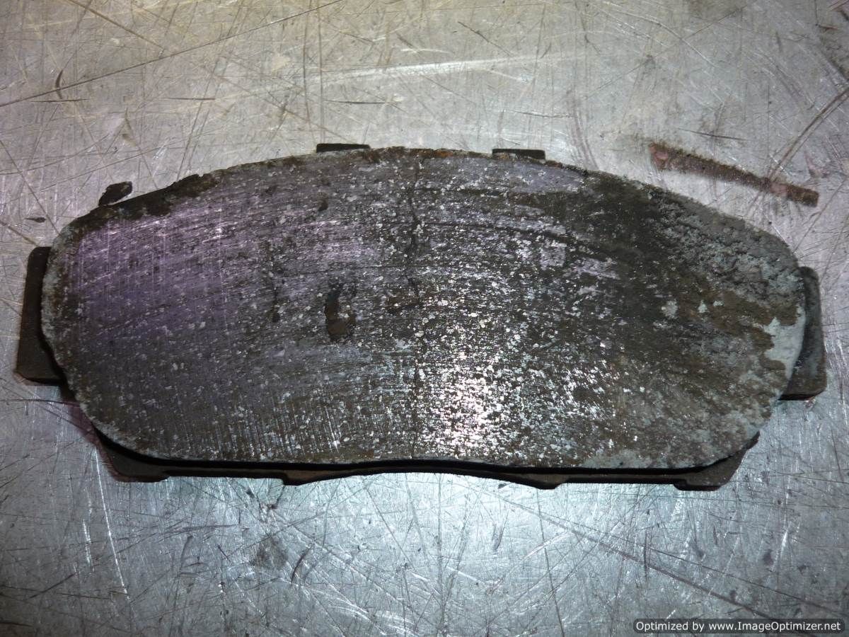
The leading edge of the pads had just disintegrated
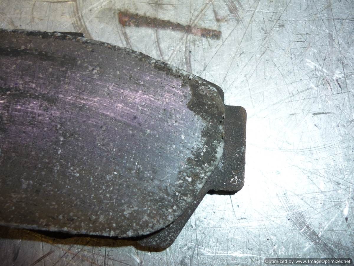
I have decided to go to a 2 pad/rotor set up. I will get a set of race pads and rotors before the next event.
In other news the knuckles and rotor shields are at the power coaters, i should be picking those up tomorrow.
The extended studs arrived today. I also have a complete set of stainless clamps for the axle shaft CV boots, I plan to rebuild the cv's with redline CV2 grease.
 07-23-2014, 01:20 AM
#37
Honda-Tech Member
Thread Starter
Join Date: Jun 2014
Location: Australia
Posts: 83
Likes: 0
Received 0 Likes
on
0 Posts
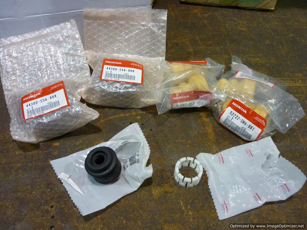
Everyone likes pictures of OEM Honda parts,
1) Front wheel bearings
2) Type R Bumpstops
3) Shifter plastic bush
On Saturday we test fit one of ChargeR's 15" x 9" +36 949Racing rims on the front.
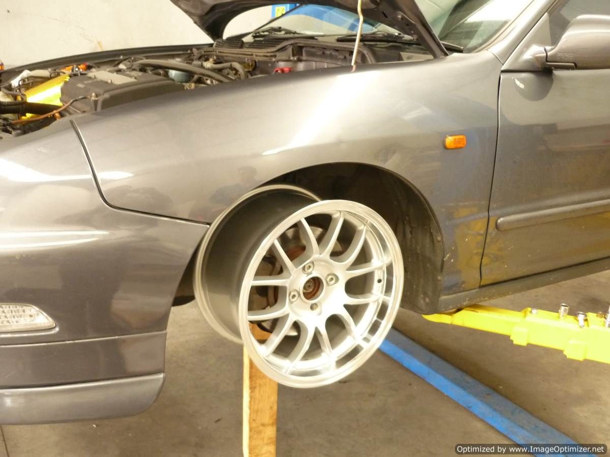
Looks proper in the wheel arch and i'm pretty keen to get a set shot with Semis for track work.
1) Front wheel bearings
2) Type R Bumpstops
3) Shifter plastic bush

On Saturday we test fit one of ChargeR's 15" x 9" +36 949Racing rims on the front.

Looks proper in the wheel arch and i'm pretty keen to get a set shot with Semis for track work.
07-25-2014, 09:28 PM
#38
Honda-Tech Member
Thread Starter
Join Date: Jun 2014
Location: Australia
Posts: 83
Likes: 0
Received 0 Likes
on
0 Posts

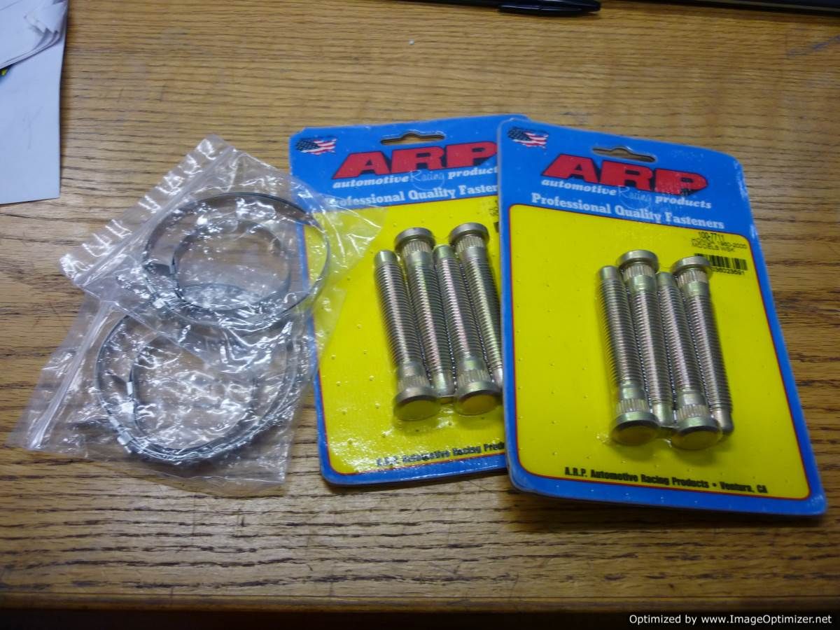
The uprights are back from powder coating, like the RTAs, they look a million bucks. If you're rebuilding your suspension it's well worth the time to get parts powdercoated vs bombing them with a rattle can.
I pressed ARP extended wheel studs into the hubs as I plan to run small wheel spacers on the front in the future.
There's been a hold up with the Mfactory parts and it's looking like another 2 week delay until I get the new suspension set up installed. Bummer.

Today I stripped the sound deadening out of the car. I didn't take any great pictures but I'm sure you all know what went down. The box of sound deadening weighed 18kgs once I was finished, so a decent weight saving!
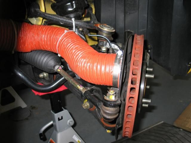
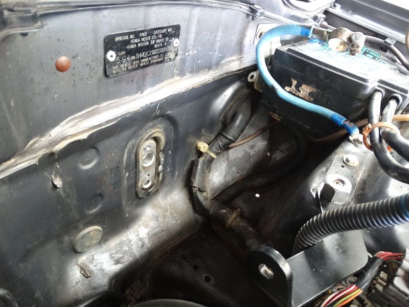
Here's a recent shot of the engine bay, you can see the air box in place with it's heat reflective tape.

Here's a close up of the 40/40 bias valve. I'm loving the feel of the brakes with the ABS system removed. The pedal feel is better and the car brakes nice and straight.
 07-31-2014, 03:57 AM
#39
Honda-Tech Member
Thread Starter
Join Date: Jun 2014
Location: Australia
Posts: 83
Likes: 0
Received 0 Likes
on
0 Posts
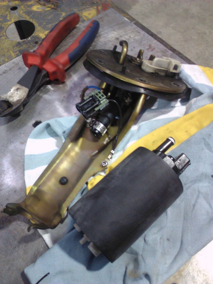
Today I swapped out my fuel pump for a Walbro unit.
When i first got the car it had fuel surge issues, I replace the fuel pump with a cheap no brand replacement from Repco.
Recently I have been having issues with the pump cutting out and preventing the car from starting. This gets really old really quick!
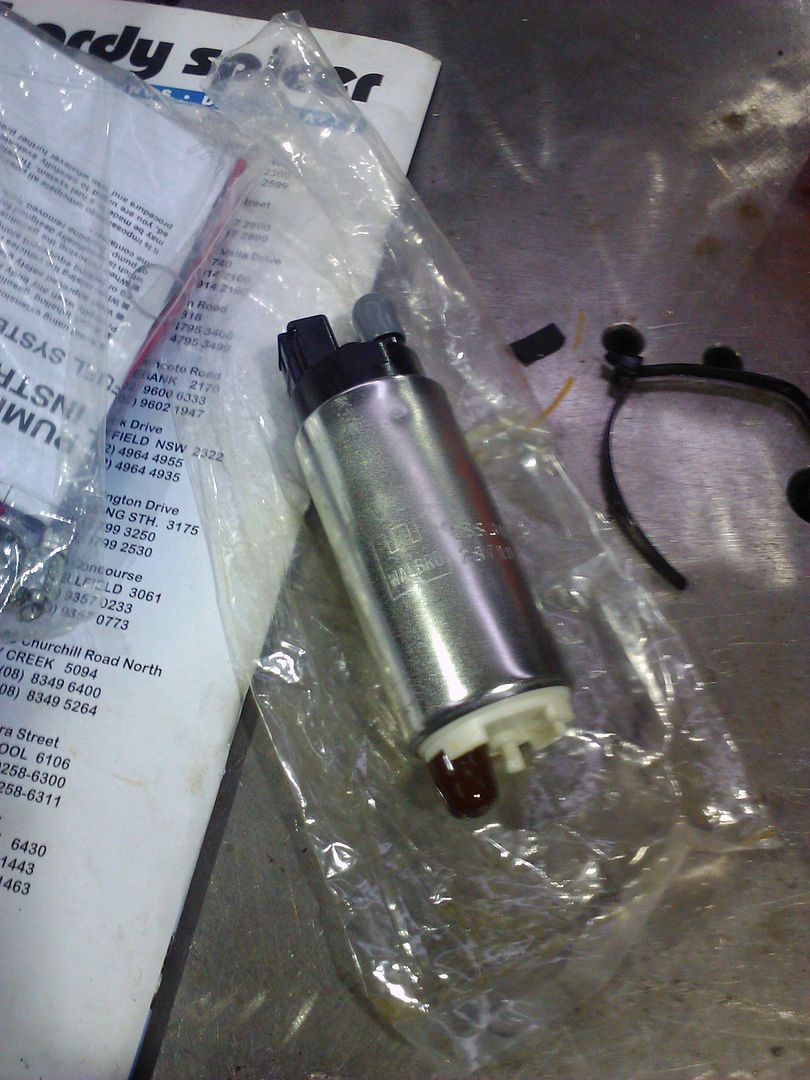
I was glad to see the Walbro came with an insulating sleeve to prevent vibrations and cut down on some of the noise transmitted to the cabin.
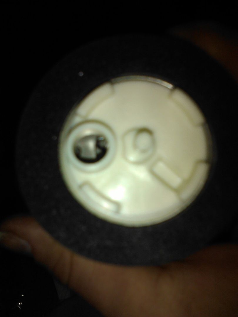
Cheap fuel pumps have plastic fins
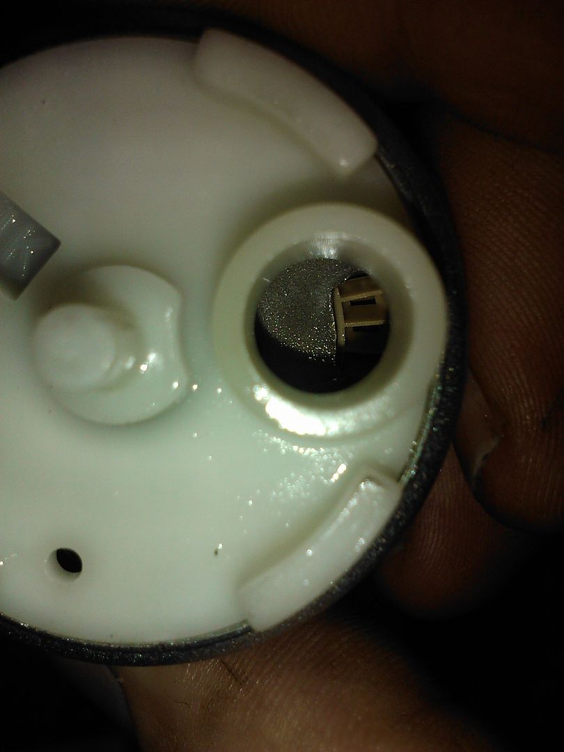
Good fuel pumps have steel gears
 08-02-2014, 01:18 AM
#40
Honda-Tech Member
Thread Starter
Join Date: Jun 2014
Location: Australia
Posts: 83
Likes: 0
Received 0 Likes
on
0 Posts
One of the biggest draw back to the Vti-r shell is that it has a sunroof. I have read that the sunroof components weigh about 15 kg, obviously this weight is concentrated at the highest part of the car.
I'm trying to get the weight of the car down as much as possible, lowering the COG height is a big priority as well.
The weight is one issue, another is the stiffness of the roof panel. The steel bracketry that supports the sunroof probably supports the roof skin a little but it's not ideal.
I did some research on Sunroof delete kits and failed to find anything that was simple yet didn't look like a total hack job.
I came across a company in the US that made a carbon panel which would be perfect except you can't actually buy them at the moment.
That company also required the installer to weld to the roof panel and fix flimsy looking brackets to hold the panel in place.
Sure you would have a carbon panel sitting there but it would do little to support the roof skin
I decided that I could come up with something better myself.
I wanted a panel that:
1) Followed the original contour of the roof
2) Was easy to install
3) Increased the stiffness of the roof panel
4) Looked tidy
I made contact with a composites expert and arranged for a plug and mold to be made. He seemed confident we could come up with a panel that could be bonded into place.
This weekend it's all coming together so I started preparing the car
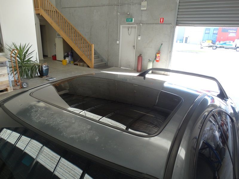
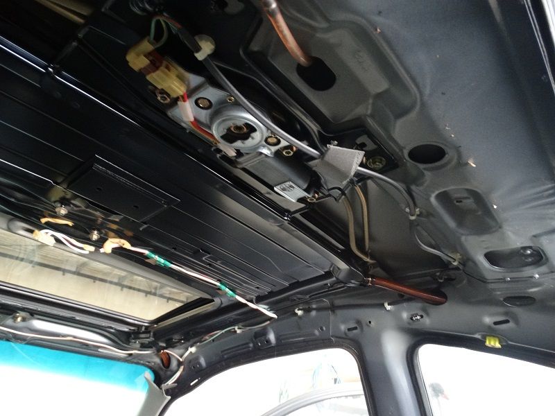
Head liner removed; I've had the interior of this car apart so many times now I've got removing the panels down to an art form. I thought removing the headlining would be a time consuming task but I was pleasantly surprised I had the whole lot out in a hour.
This is what you are left with
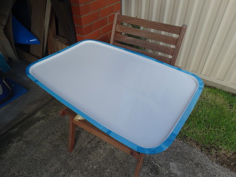
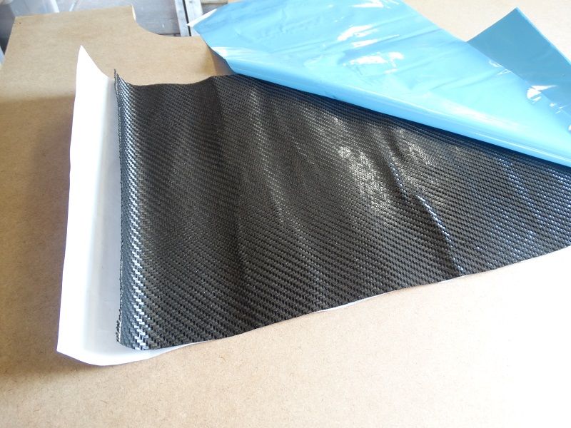
Here is the Sunroof panel mold receiving it's final preparation before the carbon is laid down. We are doing a lay up tonight and if it comes out alright we will be bonding it into the roof tomorrow.
The material we are using is from Advanced composites, it's prepreg material; 200g/sm, 3k, 2x2 twill for those carbon aficionados
I'm trying to get the weight of the car down as much as possible, lowering the COG height is a big priority as well.
The weight is one issue, another is the stiffness of the roof panel. The steel bracketry that supports the sunroof probably supports the roof skin a little but it's not ideal.
I did some research on Sunroof delete kits and failed to find anything that was simple yet didn't look like a total hack job.
I came across a company in the US that made a carbon panel which would be perfect except you can't actually buy them at the moment.
That company also required the installer to weld to the roof panel and fix flimsy looking brackets to hold the panel in place.
Sure you would have a carbon panel sitting there but it would do little to support the roof skin
I decided that I could come up with something better myself.
I wanted a panel that:
1) Followed the original contour of the roof
2) Was easy to install
3) Increased the stiffness of the roof panel
4) Looked tidy
I made contact with a composites expert and arranged for a plug and mold to be made. He seemed confident we could come up with a panel that could be bonded into place.
This weekend it's all coming together so I started preparing the car

Head liner removed; I've had the interior of this car apart so many times now I've got removing the panels down to an art form. I thought removing the headlining would be a time consuming task but I was pleasantly surprised I had the whole lot out in a hour.
This is what you are left with

Here is the Sunroof panel mold receiving it's final preparation before the carbon is laid down. We are doing a lay up tonight and if it comes out alright we will be bonding it into the roof tomorrow.

The material we are using is from Advanced composites, it's prepreg material; 200g/sm, 3k, 2x2 twill for those carbon aficionados

 08-09-2014, 04:47 AM
#44
Honda-Tech Member
Thread Starter
Join Date: Jun 2014
Location: Australia
Posts: 83
Likes: 0
Received 0 Likes
on
0 Posts
Today I removed the air conditioning components from the car
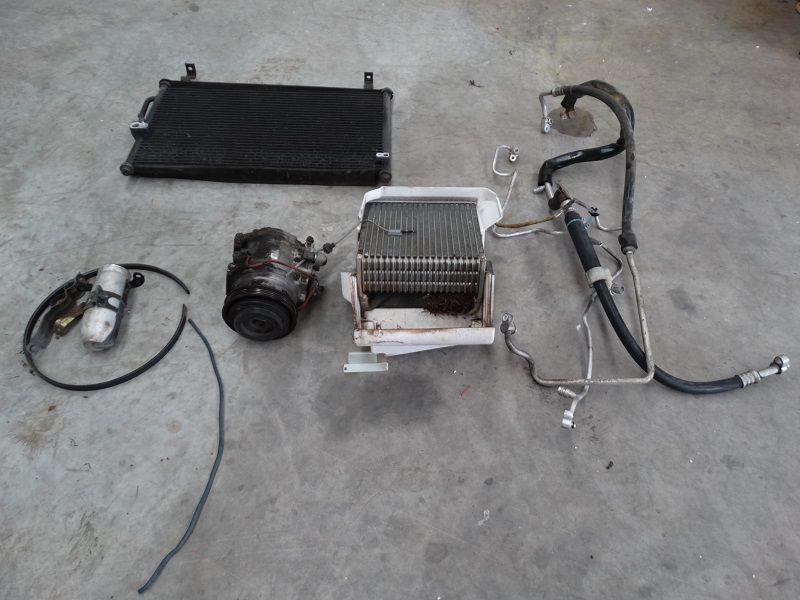
Although the weight loss is significant, i'm also grateful for the reduction in components from the engine bay.
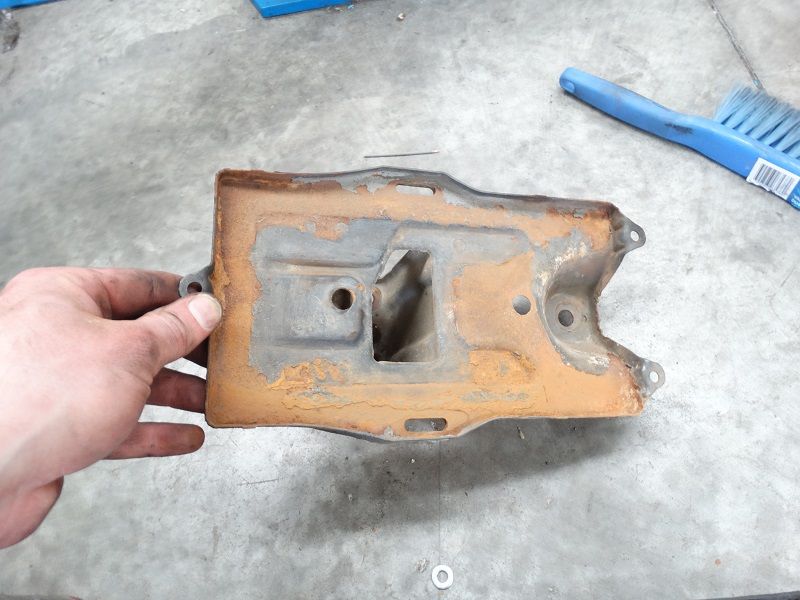
When I removed the battery to access the last of the AC lines I found the area under the battery tray had accumulated leaves and dirt, I gave the area a bit of a clean out.
The battery tray was pretty corroded. I didn't have rust killer or metal primer organised today so I will treat this rust another time.
I replaced the shifter plastic cage/bush. IMO this has a greater impact on the feel of the shifter than the hardrace urethane shifter bushes.

The carbon sunroof panel has been cured and if all goes well I should be posting some pictures of it's installation tomorrow!

Although the weight loss is significant, i'm also grateful for the reduction in components from the engine bay.
When I removed the battery to access the last of the AC lines I found the area under the battery tray had accumulated leaves and dirt, I gave the area a bit of a clean out.

The battery tray was pretty corroded. I didn't have rust killer or metal primer organised today so I will treat this rust another time.

I replaced the shifter plastic cage/bush. IMO this has a greater impact on the feel of the shifter than the hardrace urethane shifter bushes.

The carbon sunroof panel has been cured and if all goes well I should be posting some pictures of it's installation tomorrow!
08-15-2014, 01:26 AM
#45
Honda-Tech Member
Thread Starter
Join Date: Jun 2014
Location: Australia
Posts: 83
Likes: 0
Received 0 Likes
on
0 Posts
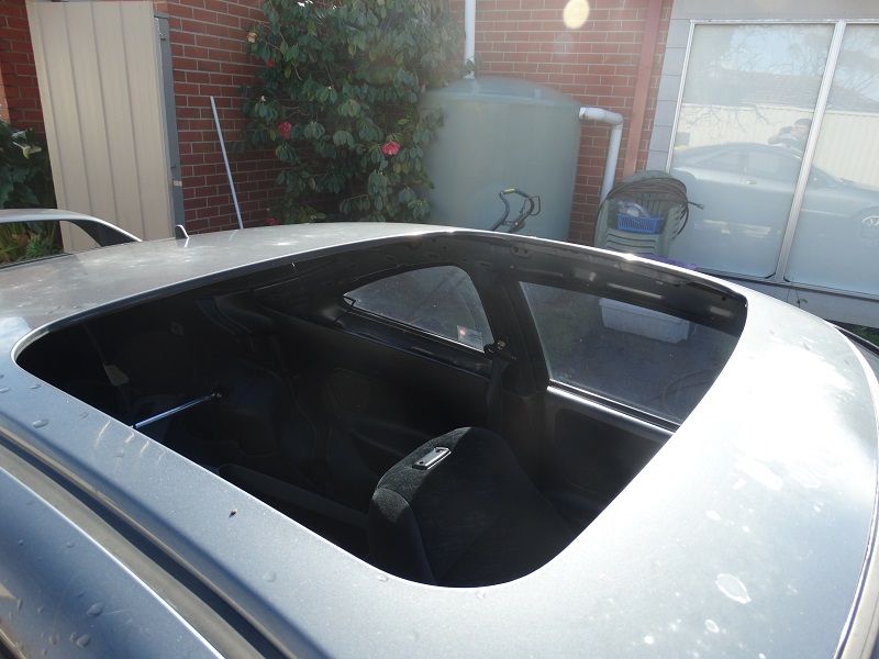
Although the sunroof install was planned for last Sunday the weather in Melbourne took a turn for the worst delaying our progress, however the panel is now installed
and I couldn't be happier with the result!
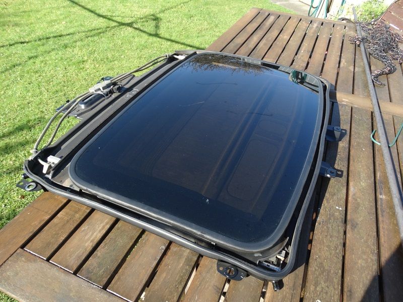
Once the headlining is out, the sunroof can be removed easily
This is what you remove, the sunroof assembly including the motor and rails weighs around 15kg so removing it gives a significant weight saving.
Then we masked the roof around the sunroof cavity
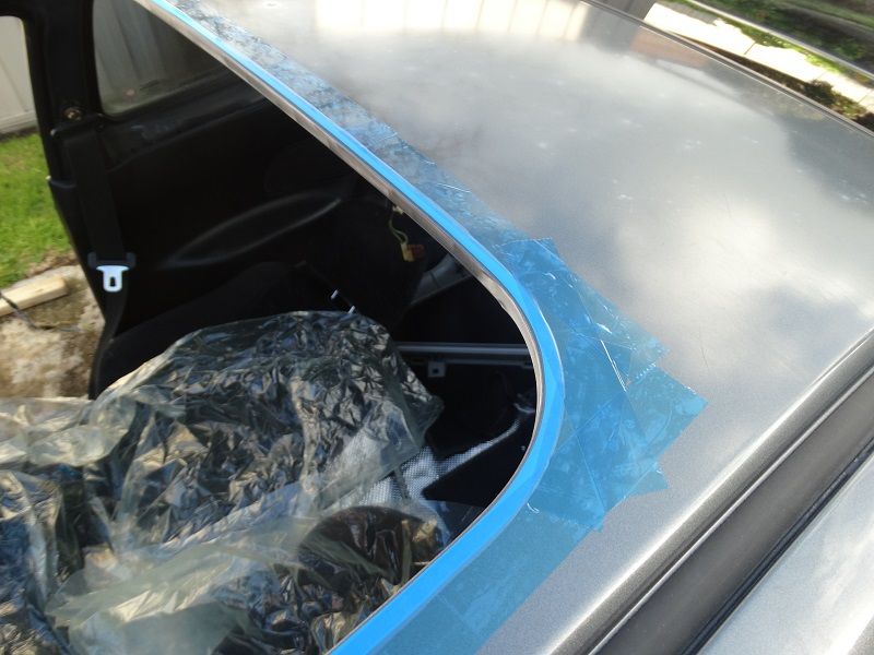
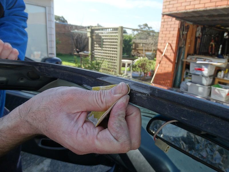
Next step was to sand the return on the roof back to bare metal. This gives the adhesive a good surface to bond to
Now we drop the new carbon panel into place, we used large clamps to hold the panel securely
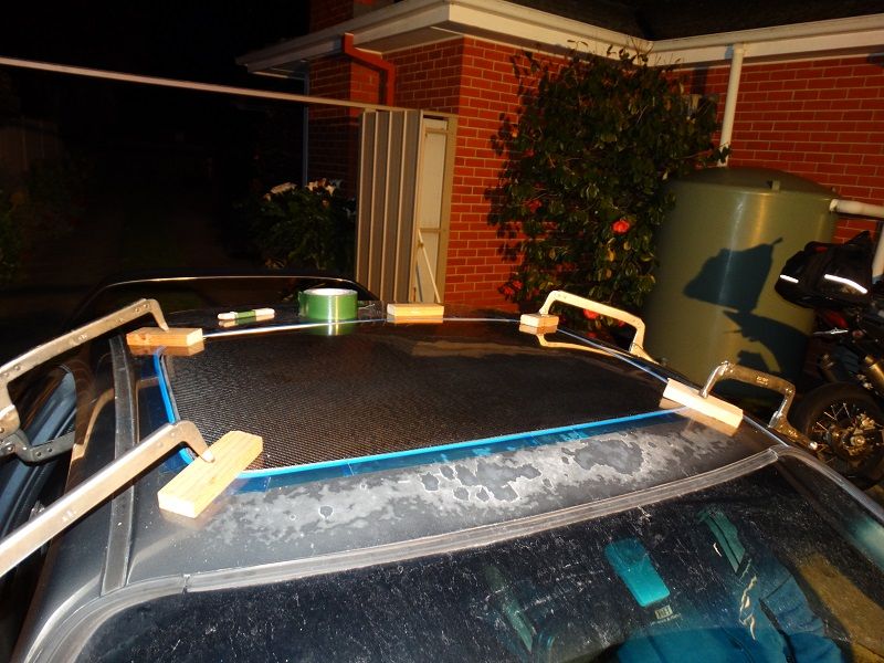
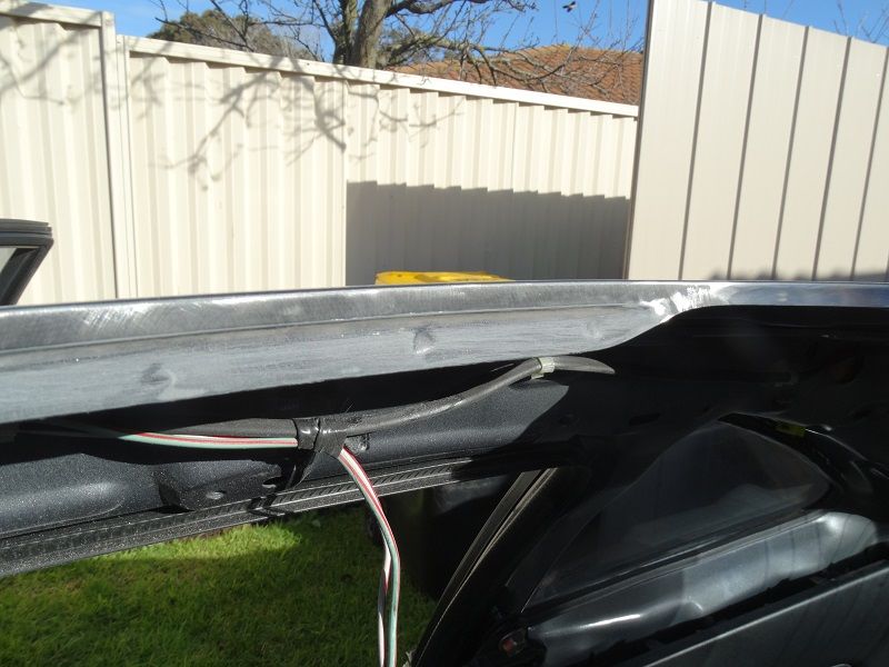
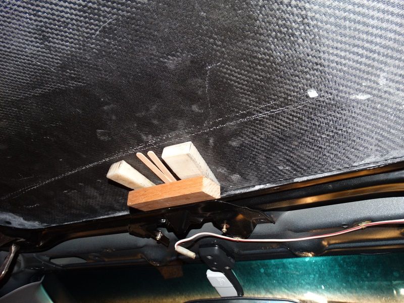
I re-installed the sheetmetal base of the sunroof and used that as a ledge to shim the panel level with the roof
Once the panel was sitting correct we used sikaflex to bond it to the roof. We kept the clamps in place until the sikaflex cured to full strength.
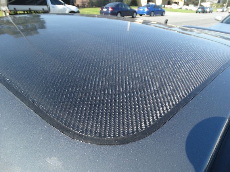
The finished result
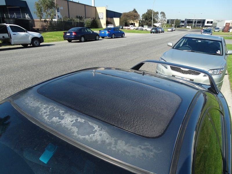
Even just driving the car around the streets the improvement in chassis stiffness is noticeable! The feel of the car has improved and this modification has affirmed my love for the Dc2 chassis. It seems that with every kg that
I remove I'm rewarded with improved feel and better response to driver inputs.
and I couldn't be happier with the result!
Once the headlining is out, the sunroof can be removed easily

This is what you remove, the sunroof assembly including the motor and rails weighs around 15kg so removing it gives a significant weight saving.

Then we masked the roof around the sunroof cavity

Next step was to sand the return on the roof back to bare metal. This gives the adhesive a good surface to bond to


Now we drop the new carbon panel into place, we used large clamps to hold the panel securely

I re-installed the sheetmetal base of the sunroof and used that as a ledge to shim the panel level with the roof
Once the panel was sitting correct we used sikaflex to bond it to the roof. We kept the clamps in place until the sikaflex cured to full strength.
The finished result


Even just driving the car around the streets the improvement in chassis stiffness is noticeable! The feel of the car has improved and this modification has affirmed my love for the Dc2 chassis. It seems that with every kg that
I remove I'm rewarded with improved feel and better response to driver inputs.
08-16-2014, 10:03 PM
#46
Honda-Tech Member
Thread Starter
Join Date: Jun 2014
Location: Australia
Posts: 83
Likes: 0
Received 0 Likes
on
0 Posts
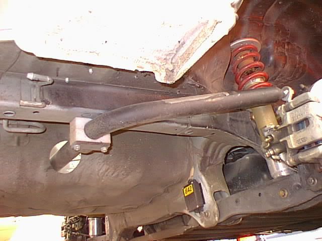
With ChargeR's help I installed the modified RTAs yesterday.
My old RTA bushes have seen better days
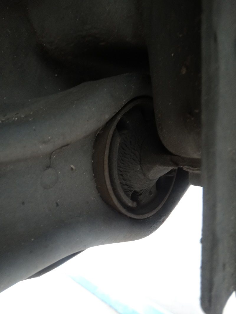
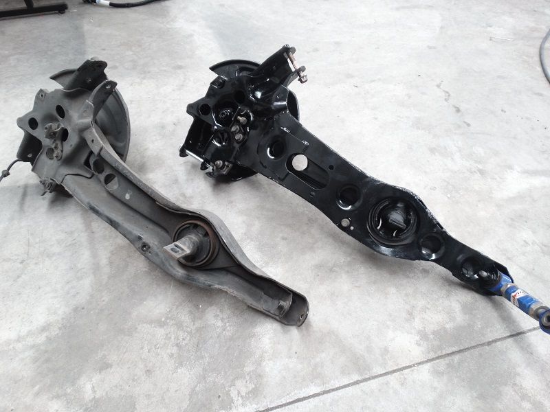
Here is a side by side of the standard RTA and the modified version
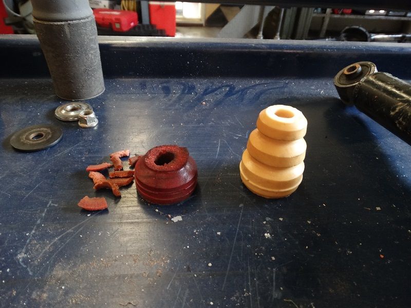
While I had the shocks out I took the time to swap in the new rear bumpstops. As you can see there wasn't much left of the old bumpstop. I think i ended up cutting another division of the bumpstop off after this picture was taken
There was no dramas installing the new trailing arms and the handbrake cable routing through the gusset plates work out well (I did test this before making the plates).
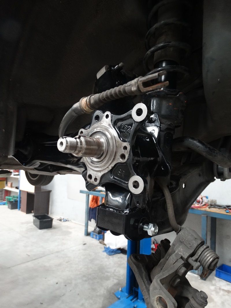
Here is a direct comparison showing the angle of the LCA before and after
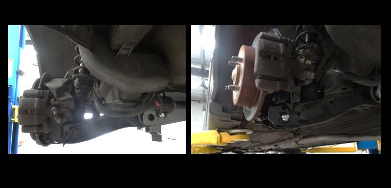
The money shot
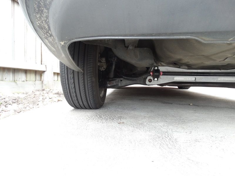
I'm going to hold off giving a full review until I take the car out on track again but I will say that I am very happy with the results and If I had to give an analogy to describe the change I would say
it is a similar feeling to changing from the 14mm anti-roll bar to the 23mm anti-roll bar.
This is pretty much what you would expect as I have effectively increased the roll stiffness by ~22%
The difference between relocating the LCA mount and going to say a 30mm anti-roll bar is that the two wheels retain the ability to track independently
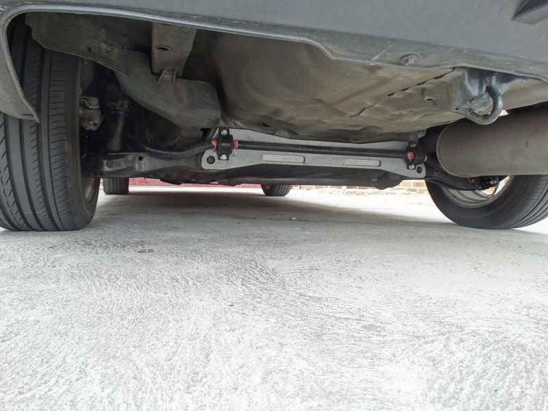
By modifying the roll centre position I can have the roll stiffness I want without having to do something like this:
Which is effectively a De Dion Tube conversion haha!
My old RTA bushes have seen better days

Here is a side by side of the standard RTA and the modified version

While I had the shocks out I took the time to swap in the new rear bumpstops. As you can see there wasn't much left of the old bumpstop. I think i ended up cutting another division of the bumpstop off after this picture was taken

There was no dramas installing the new trailing arms and the handbrake cable routing through the gusset plates work out well (I did test this before making the plates).

Here is a direct comparison showing the angle of the LCA before and after

The money shot


I'm going to hold off giving a full review until I take the car out on track again but I will say that I am very happy with the results and If I had to give an analogy to describe the change I would say
it is a similar feeling to changing from the 14mm anti-roll bar to the 23mm anti-roll bar.
This is pretty much what you would expect as I have effectively increased the roll stiffness by ~22%
The difference between relocating the LCA mount and going to say a 30mm anti-roll bar is that the two wheels retain the ability to track independently
By modifying the roll centre position I can have the roll stiffness I want without having to do something like this:

Which is effectively a De Dion Tube conversion haha!
Last edited by DailyTrackDc2; 08-17-2014 at 12:16 AM.
08-16-2014, 10:25 PM
#47
Honda-Tech Member

Amazing work, great thread. I'd love to do the same for the roof panel on my gsr. I also don't like the options available here. You could duplicate the one you made and sell it quite easily here I would imagine.
Last edited by Runnerdown; 08-17-2014 at 10:03 PM.
08-17-2014, 08:13 PM
#48
Trial User

Join Date: Aug 2014
Posts: 1
Likes: 0
Received 0 Likes
on
0 Posts
This is an incredible thread, I got sucked in when I saw how similar my car is to what yours started off as. And how you did the same upgrades that mine had been fitted with before I bought her. Excited to watch this progress further!
